This thread has been locked.

If you have a related question, please click the "Ask a related question" button in the top right corner. The newly created question will be automatically linked to this question.

TPS51206: S3 + S5 Power State Control for DD4 1.2V?

Part Number: TPS51206

Hi all, 

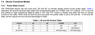
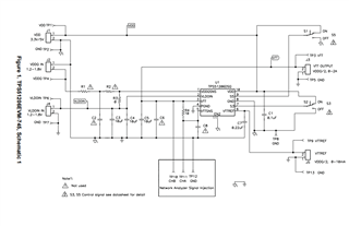
I am investigating the use of the TPS51206 for a DDR4 application at 1.2V logic. Section 7.4.1 of the datasheet lists the power states needed to control the device but I have a few questiosn regarding these two pins:

1. How do you properly terminate the S3 and S5 pins for 1.2V logic?

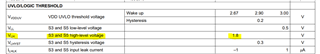
2. What is the proper logic control for DDR4 using the S3 and S5 pins? What voltage levels do the HI and LO states need to be at 1.2V as this is not clearly defined in the datasheet. 

Let me know your thoughts whenever possible and I hope to hear back from you soon

  • Hi Filipe,

    The S3 and S5 pins have a VLH (logic level high) threshold of 1.8V so you would likely need to connect these to either VDD or some other external voltage. In a typical application VDD would be 3.3V or 5V.

    To have control over these pins in a closed system you could use pull-up resistors in combination with an open-drain connection from some host IC. On our EVM for this part, we use simple switches that you can toggle on and off directly on the board. Or if you don't plan to use any state besides VTT fully ON, you can just tie these pins to a voltage >1.8V.

    TPS51206EVM Schematic from the User's Guide:

    Regards,

    James