This thread has been locked.

If you have a related question, please click the "Ask a related question" button in the top right corner. The newly created question will be automatically linked to this question.

LM3643: Review schematics for LED switch

Part Number: LM3643

Hi Sir,

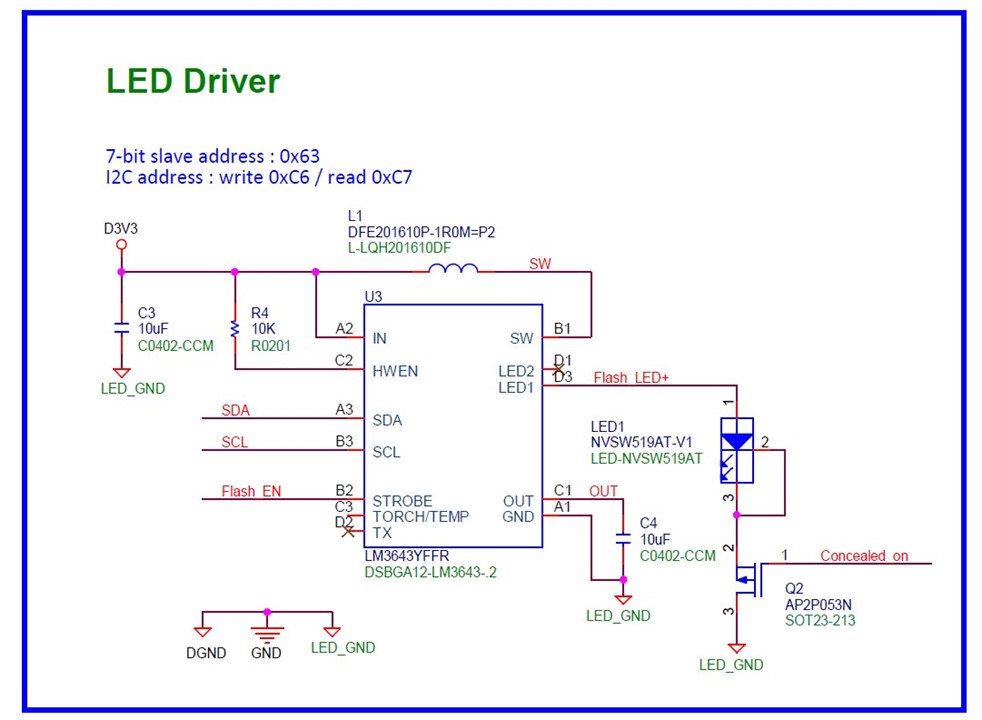
My customer would like to add an external P-MOS to do the LED switch.
Could you please help to review the below schematics and advise comments?

My customer also has some questions as below.
The default condition is the LED light working normally by LM3643 controlled and the test step is as below.
Step 1:  Only turn off the Q2, and the LED lights out.
Step 2:  turn on the Q2 again.

Is the LED light working normally after step 2?
Do we need to reset the I2C setting after step 2? or concerned about any side effects on the LM3643 (ex: H/W reset, OVP, or other)?

Flash_LED+ voltage = 3V, ILED = 700mA

  • Hi Henry,

    Please see my comments below:

    1. If they want to use the external P-MOS to shut down the LED during operation, the output voltage will go high and try to generate the current for LED, after the voltage go beyond 5V, the device will enter over voltage protection and turn off the internal FET, it can cause the device enter shutdown mode to protect itself and need to be reset again for normal operation. You can see more details on section 9.4.5.3.

    2. Actually, I don't understand the meaning of using the external FET, if they want to control when the LED light up and turn off, they can use STROBE pin under IR mode to use external signal to control the LED. You can see more details on section 9.3.3.

    Thanks!

    BRs,

    Ives Li