


Other Parts Discussed in Thread: BQ76200
Hi
The customer is planning to design a BMS with integrated output function. The rough block diagram is as attached. Please help confirm whether this design can operate normally.
The requirements are as follows:
1. The battery pack is 13S with a rated output power of 6000W (AFE decided to use bq76952)
2. Add a set of integrated MOS controls, tentatively using bq76200
3. PM+ is the positive terminal of the secondary battery pack
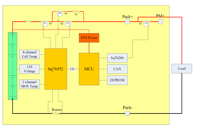
1, Is the attached block diagram feasible?
2, Is the control MOS direction of the package reasonable?
3, When the main battery pack MOS (Q1, Q2) are all turned off, can the secondary battery pack MOS (Q3) be turned on normally?
4, If this solution is feasible, how to deal with the BAT and PACK pins of bq76200, and which channel Q3 uses to drive
5, When switching, prepare to turn off the main battery pack Q1 → turn on Q3 → output the secondary battery pack. Is this logic reasonable?
Waiting for your reply.
Thanks
Star
