This thread has been locked.

If you have a related question, please click the "Ask a related question" button in the top right corner. The newly created question will be automatically linked to this question.

TPS745-Q1: Questions about Vout VFB Cff

Part Number: TPS745-Q1
Other Parts Discussed in Thread: TPS7A8300, TPS745

Hi,

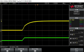
I find Cff will make start-up time longer.According to the application note https://www.ti.com/lit/an/sbva042/sbva042.pdf?ts=1698638510370, it's normal. Though it take TPS7A8300 is used in this example, TPS745 works the same.Green one is VFB and yellow one is Vout.

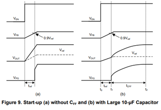
With Cff, you can see VFB rises and stays at Vref. It seems to have nothing to do with Vout. The application note mention that. "During the tref time, VOUT tracks VFB. VFB is controlled by the LDO feedback loop and is forced to match Vref. "

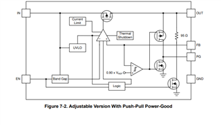
My questions is why VOUT tracks VFB and how the feedback works if VFB is forced at one voltage level?

  • Hi Zehui,

    The output of the LDO is connected to the Feedback through a resistor divider in order to set the voltage. The error amplifier is there to compare the Vref and the Vfb and will drive the gate voltage of the FET higher or lower depending on the result of the comparison. For example, if a load transient were to happen and suddenly the Vout drops in order to supply the large load, the error amplifier will notice this change in Vfb compared to the Vref and adjust the LDO to get to a constant regulation as quick as possible. 

    About tref, this is momentary, and Vout will then go to the desired output. This is set in place in case you want a slow start to the LDO so Vout will track Vref in that period of time. 

    I hope this helps answer your question and provides some clarification. Please let me know if you have any further questions.

    Thank you,
    Josh Nachassi 

  • Hi Josh,

    Do you have a internal structure diagram to explain how it works? I don't see anything about the Tref and the soft-start in the datasheet.

    I guess it's the same as those ICs which have a SS pin. Css charges and Vss rises, and Vref tracks Vss.

    Questions:

    1.How does Vout track Vref? I didn't find any structure to do the work.

    2. It seems VFB has the same ramp slope.I wonder if it controls the Vout at the start-up somehow. Normally, VFB is controlled by Vout, so it sense the change of Vout to do the feedback work.

    3.As you can see at start-uo figure, when VFB reach the max, Vout is still rising.So at this moment, the feedback cannot work, otherwise it will find a under-voltage event. When does the feedback start to work?

  • Hi Zehui,

    In terms of the LDO, the Vref is the stable voltage that the error amplifier is comparing the feedback to. In this case, for this ldo, the internal structure includes a Band Gap instead of a reference voltage but the idea is the same. This voltage is constant and shouldn't change so when there is a change on the output voltage the error amplifier looks at this voltage as the control in order to adjust the Rds of the FET to control the flow of current depending on if there needs to be more Vout or less. So Vout technically tracks Vfb and Vfb is compared against Vref, or in this case the bandgap. 

    Here is the block diagram of the device to help you understand the internals more. 


    2. Vout and Vfb will also have a similar ramp rate because Vout and Vfb will be tied together with a resistor divider network. 

    Vout = (1+r1/r2)*Vfb .

    3. Every one of our devices has a startup graph that I would look at if you want to know when the part will start regulating. The reason that Vout continues greater than Vfb is because of the resistor divider. You must wait until the the device has completely started up for it to be in regulation.

    Please let me know if you have any further questions.

    Thank you,

    Josh Nachassi

  • Hi Josh,

    2.If we use Vout = (1+r1/r2)*Vfb, we must make sure Vout is the only source and Vfb is high-impedance.But I guess Vfb is not high-impedance at start-up becauseI find no matter whether Cff exists or not,VFB has the same ramp slope. How come it rise the same if Vfb is high-impedance? However, I do measure the Vout and Vfb without Cff. Vout is exactly (1+r1/r2)*Vfb. This really confuses me.

    3.Yes, I really want to know how it starts. It will be very kind of you if you could share your opinion.

  • Hi Zehui,

    Thank you for these questions. If you are using a CFF that is too large then it is possible to change the ramp rate of VFB and slow down startup time of the LDO because there is an additional RC time constant associated with it. You can get away with using a small CFF and not affecting the start-up time. In our data sheets we usually have information regarding the CFF nominal rating to make sure that startup time is consistent. 

    The reason that Vout = (1+r1/r2)*vfb is just because of a voltage divider between the resistors r1 and r2 and Vout and Vfb. The Vfb is constant during normal regulation so you just have Vout(r2/(r2+r1)) = VFB and then if you move the resistors to the right of the equation you will get (1+r1/r2)*Vfb = Vout.

    Hope this helps, please let me know if you have any further questions.

    Thank you,

    Josh Nachassi