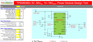
I designed the circuit per Power Module Design Tool with small difference in C and R's to match standard passive components that are available. However, the output shows 1 Volt (0.999 V) and not 5 V as I was hoping and expecting. Please help...

This thread has been locked.
If you have a related question, please click the "Ask a related question" button in the top right corner. The newly created question will be automatically linked to this question.
I designed the circuit per Power Module Design Tool with small difference in C and R's to match standard passive components that are available. However, the output shows 1 Volt (0.999 V) and not 5 V as I was hoping and expecting. Please help...

Hello Nayab,
It seems as if your enable divider has RENT = 1000 ohms and RENB = 0.619 ohms. This creates a voltage divider in which EN will only receive 0.002 V. According to the datasheet, EN needs to be above 1.365 V to guarantee proper operation. Changing RENB to a high enough value to push EN above 1.365 V will properly turn on the part. Also keep in mind per section 7.3.7, the impedance of the parallel combination of RENT and RENB needs to be in the 100 kOhm range to properly utilize the SYNC function of the part if that is in your application's purview.
Please let me know if this helps,
Joshua Austria
Thanks for the quick reply. In my application EN is directly connected with Vin but I couldn't figure out how to configure the TI's Power Designer tool to use that. So in my actual design RENT = 0 ohms, and RENB is infinity.
Do you know if this device can operate in positive boost mode (Vin < Vout)? I see examples of negative Vout but not positive Vout in boost mode. Thanks
Hi Nayab,
Thank you for that extra information. This device is a buck device and is not recommended to be operated where VIN < VOUT. There is no positive boost mode for this device. This device does have the capability to be configured into an inverting buck boost as shown in section 8.2.2 of the data sheet. If you want more information on this feel free to check out this app note on the general case of turning a buck module into an inverting buck boost device: https://www.ti.com/lit/pdf/snvaa63
Please let me know if this helps,
Joshua Austria