Hello,
This thread has been locked.
If you have a related question, please click the "Ask a related question" button in the top right corner. The newly created question will be automatically linked to this question.
Hello,


Hello
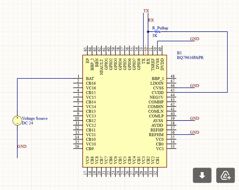
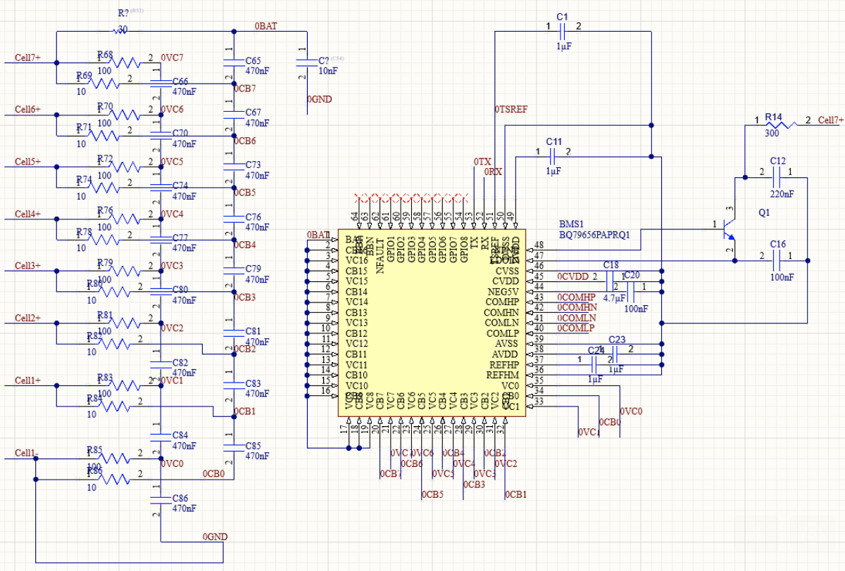
It looks like you do not have any GND nets on any of your decoupling caps. Please see the below diagram and add gnd nets to all of your decoupling caps where GND is required.AVSS, DVSS, and CVSS are all GND reference, you need to actually attached them to a GND path as well. Also, it seems the NPN circuitry is incorrect. You should have a LDOIN cap referenced to GND near the pin and a capacitor on the collector of the NPN near the NPN collector as well referenced to GND. I believe the GNDing of the PCB is a problem since I do not see any GND net.
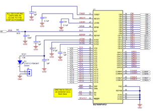
On page 187 of the BQ79656 datasheet you should see the proper circuitry. Right now your capacitors on the NPN emitter and collector share the same node, they should not.
Thanks,
Chase
Hello,
I am another member of the electrical team working with Asad on this custom battery management system. Thank you for the reply. We do actually have all of those decoupling caps referenced to ground as in the datasheet, and our NPN circuitry is as you described. I simply forgot to add a GND net label in the schematic that I sent you. Our circuitry matches your descriptions in your response as far as I can tell.
We ordered new NPN transistors that are in spec with the TI evaluation module that you sell to test this chip, but that is the only lead we have on what to try next. Thanks again for your response, I hope to hear more from you soon about your thoughts.
Best,
Silas Schroer
If the circuit matches the schematic and diagram above, you are good to go. Since LDOIN powers the IC, it is essential the NPN is properly selected with sufficient headroom to power the device. If the regulators aren't working, then it is definitely a power issue. You need the capacitors on each pin and close to the pin of each device. It is important to build the entire circuit fully and then test rather than building subsets of the circuits piecewise.
Ok, makes sense. I will check back in when we get the transistor. We are doing all of this testing on a breadboard before designing our PCB. Will this chip function on a breadboard/breakout board if the circuit is correct?
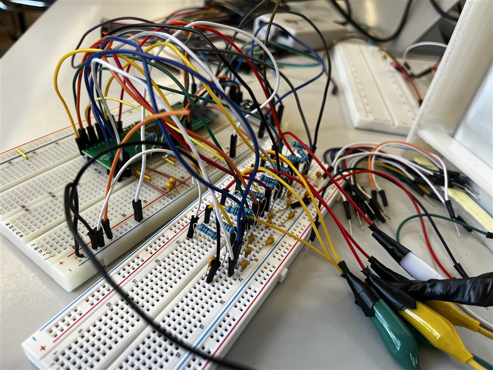
Hey Chase, thanks for the reply. We got the NPN and it is well within spec to power the device. We are still having a lot of trouble with the regulators of the device. LDOIN pin is sitting at 4.5 volts, CVDD is sitting at 4.5 volts, DVDD is sitting at 400 mV. I have attached pictures of our breadboard test circuit connected to 6 battery cells in series. Do you see any issues with how we've set up the breadboard circuit? Do we need to design a PCB to meet the strict requirements for Coupling Capacitor placement and Grounding schemes?
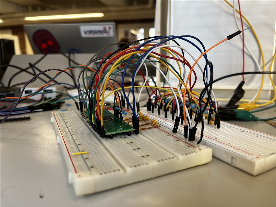
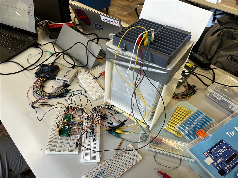

Hello,
It appears there is still issues with the NPN circuitry since LDOIN is only 4.5V when it should be 6V. I would try isolating just this subcircuit and debug from there.
Thanks,
Chase