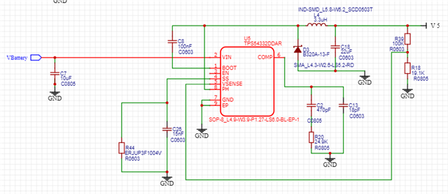
above is the circuit we have, we experience loud humming noise from the inductor, the higher the load , the louder the noise.
please help
This thread has been locked.
If you have a related question, please click the "Ask a related question" button in the top right corner. The newly created question will be automatically linked to this question.
just to add on, before this, the sound is pretty random, some PCBA have and some do not, recently the team done some changes
1. trying to save some sleep mode current by increasing the R39 & R18.
2. remove resistor pair for Boot pin, as the data sheet show that if the Boot pin is floating, it is default enable.
Hello Allen,
1. There is no resistor of BOOT-pin in your schematic, and Boot-pin cannot be float, do you mean EN-pin?
2. Your Cout seems quite small, only 1*22uF. Suggest to increase Cout like 2*47uF. Also Cin is quite small, only 1*10uF, please increase Cin to make sure input voltage stable.
3. Did you checked your Vin/Vout/SW/IL waveforms? Whether has unstable phenomenon? Suggest to follow our webench tool to design the circuit.

Dear Miranda,
1. yes is the EN pin that we made floating, will that be any concern?
2. may i know the propose Cin ?
3. any concern on the R39 & R18 ? Do we need to a 15nF capacitor parallel with R39? ( refer to Figure 2.0 )
to update the issue, there is a 100uF at 5V, was for other circuit. And we change this capacitor to 22uF, the noise totally gone. in Total, there is 2x22uF in the circuit now.
Figure 1.0 - above is the Vout ( 5V )
Figure 2.0 - above is the Vout (5V), after add 15nF parallel to R39
Hi Allen,
1. No concern.
2. You didn't show Cin waveform, if you saw Vin was kind of unstable, please add at least 2*22uF Cin.
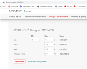
3. Could you please share your operation conditions Vin & Iout values? Webench tool could generate a recommended circuit based on Vin/Vout/Iout.
4. I didn't see concerns of R39 & R18 values. Adding 15nF in parallel with R39 could help to increase loop bandwidth and improve loop response.
5. Is your output current constant or variable? Is it possible to trigger overcurrent limit? Large Cout may cause large inrush current. And is your Vout 5V or lower than 5V? Please capture Vin, Vout, SW, IL or Iout waveforms to help us further analysis.
Hi, Miranda,
2. the Vin is from a Battery , which we have a 100uF capacitor there , seems stable
3. we try the webench tool and it give us a circuit is have big different for the inductor ( we are using 3.3uH , which webench 6.8uH ) & also all the Component at the comp side. the exisitng circuit we used seems working so far although is different from the circuit from Webench, do you think we need to change the existing circuit to follow what is from Webench?

5. the Vin is from a Battery which will be from 11.7V - 16.8V, Vout is 5V which the load is very small just with some LED blinking.
Hello Allen,
Thanks for your quick feedback, my comments are below.
2. Sure, it's OK.
3. Using smaller inductance will have larger inductor current ripple, and output voltage ripple will be larger, as described in datasheet.

I would say you can try larger inductance, the humming noise may be lower as inductor current ripple is smaller.
5. From the SW waveform you showed, seems there is a ~200Hz (~5ms period) low-frequency oscillation.200Hz is within audible frequency range (20~20kHz) that people can hear. I guess if you removed the 200Hz oscillation, the humming noise you heard may be disappeared. Have you checked where it from? Is your loading current changing with 200Hz frequency? Or your loading is constant, the oscillation is caused by loop instability? If so, please use the webench recommended circuit.