


Hi team,
I’m trying to design output-programmable SEPIC with LM3481, and facing a challenge. Would you please take a look, and provide suggestion?
The basic requirements are,
- Vin=5V
- Vout=2.5V~15V
- Iout=0.8A
I add adjustable DAC on FB pin to program SEPIC output, referring to this application note. Below is the schematics. When VDAC=2.5V, calculated SEPIC Vout=2.5V. When VDAC=0V, calculated SEPIC Vout=15V.
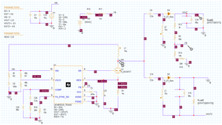
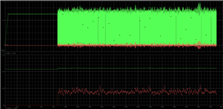
Besides from large output ripple and a bit lower output value, it worked as expected when calculated Vout=15V (VDAC=0V) and Vout=8.75V (VDAC=1.25V). But when I set VDAC=2.5V (calculated SEPIC Vout=2.5V), the SEPIC output was around 400mV. Below is the waveform I got.
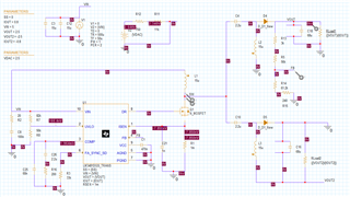
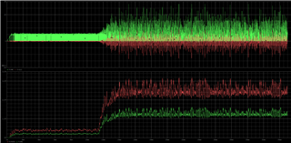
When I disconnect VDAC from FB-pin and adjusted lower feedback resistance to be 61.4k (so that it is just a simple SEPIC), it regulated Vout as 2.5V as expected (please ignore large ripple). Below is the schematics and waveform.
I cannot think of the reason why connecting to DAC made SEPIC unable to regulate the voltage, only for 2.5Vout. The difference between 15Vout and 2.5Vout that I can think of is the current direction for VDAC. when VDAC>1.275 (=VFB), the current will flow from VDAC to GND. When VDAC<1.275, the current will flow from VOUT to VDAC. But it should not affect how LM3481 regulate the output voltage level, right?
Would you please provide suggestion on possible cause?
Best regards,
Kurumi

