This thread has been locked.

If you have a related question, please click the "Ask a related question" button in the top right corner. The newly created question will be automatically linked to this question.

BQ27421-G1: Application issues of chips

Part Number: BQ27421-G1
Other Parts Discussed in Thread: EV2400, BQSTUDIO

I have a few questions about the electricity meter BQ27421.

1. Obtain the remaining power and send 0x1C: The data read is 52 00. Does 52 indicate that the remaining power is 82% (0x52=82)? What does the second byte 00 represent?

2.During the charging process, the data read by 0x1C increases from 01 00 to 16 00, and then suddenly becomes 52 00. The charging current decreases and the battery cannot be charged. The data read remains at 52 00. Why does the battery level jump? Do you need to configure parameters for the electricity meter first?

3. Read DEVICE_ How should TYPE issue commands? I tried sending 00 to read 88 7F first, and then sending 0001 to read 01 00, not 04 21 as written in the document.


  • Also, could you help me take a look at this log to see the reason for the capacity jump?

  • Hello,

    1. Yes, the data read as 52 00 should be 0x52 = 82%. There are two bytes being read due to the information for these values being contained in two registers, seen here. When 0x1C is read, you are actually reading the values from 0x1C and 0x1D.

    2. Can you please confirm if a learning cycle has been preformed on this battery?

    3. Are you using bqStudio and EV2400 to connect to the gauge? If not, the bq27241 Technical Reference Manual contains a section of how to configure parameters and send commands via command sequences:

    https://www.ti.com/lit/pdf/sluuac5 

  • Can you help me reply to this part of the question? Thank you!

  • Hello,

    Can you please specify which part of the question you are asking about?

    Regards,

    Anthony Baldino

  • 1.Could you please help me take a look at this log to see the reason for the capacity jump?
    2.Could you please help me check if the battery curve needs to be imported into the electricity meter? I couldn't find a command on how to set the battery capacity in the Technical Reference document. Could you please help me see how to set it?Be sure to provide me with a command document on how to set battery capacity, otherwise I won't be able to proceed. The current state is that the remaining battery can be read, and it will jump during charging.

    Could you please help me take a look at this log to see the reason for the capacity jump?

    Could you please help me take a look at this log to see the reason for the capacity jump?

    Could you please help me take a look at this log to see the reason for the capacity jump?

    Could you please help me take a look at this log to see the reason for the capacity jump?

    Could you please help me take a look at this log to see the reason for the capacity jump?


    2.
    麻烦帮忙看一下电量计是否需要导入电池曲线,我在Technical Reference文档中没有找到如何设置电池容量的命令,帮忙看一下怎么设置?现在状态是能够读取到剩余电量,充电时会跳变。

    Could you please help me check if the battery curve needs to be imported into the electricity meter? I couldn't find a command on how to set the battery capacity in the Technical Reference document. Could you please help me see how to set it? The current state is that the remaining battery can be read, and it will jump during charging.

    笔记
    双语对照
    jump?

  • Hello,

    How are you communicating to the gauge? If you are using bqStudio and EV2400, you can use the bqStudio software Data Memory Tab to change the design capacity. If you are not using bqStudio, these commands found below can help you configure the Design Capacity using outside communication:

    The currently set design capacity could be contributing in the jump in State of Charge since the currently set design capacity is 0x7FF4. After the design capacity and other parameters are set based on the document below, a learning cycle will need to be completed to get the correct values.

    https://www.tij.co.jp/jp/lit/pdf/slua903 

    Regards,

    Anthony Baldino

  • Could you please check if there are any issues with the code and logs? They were sent according to the documentation

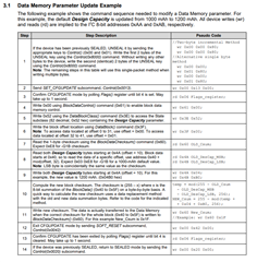
    The order of commands in document bq27421 Technical Reference 3.1

    Electricity meter code and log.txt
    unsigned int battery_ModifyDesignCapacity(void)
    {
    	uint8_t data[4]={0};
    	uint8_t dataBuf[2]={0};
    	uint8_t addr = 0x55;
    	unsigned int volt = 0;
    	uint8_t ret = 0;
    	uint8_t OLD_Csum = 0;
    	uint8_t OLD_DesCap_MSB = 0;
    	uint8_t OLD_DesCap_LSB = 0;
    	uint8_t temp = 0;
    	uint8_t NEW_Csum = 0;
    
    	DBG_STR("----------------ModifyDesignCapacity---------------");
    	data[0] = 0x06;//flags
    	ret = GPIO_I2CWriteByte(addr, data[0], 0);
    	ret = GPIO_I2CReadNByte(addr, dataBuf, 2, 0);
    	data[0] = 0x00;
    	data[1] = 0x00;
    	data[2] = 0x80;
    	ret = GPIO_I2CWriteNByte(addr, dataBuf, 3, 0);
    	data[0] = 0x00;
    	data[1] = 0x00;
    	data[2] = 0x80;
    	ret = GPIO_I2CWriteNByte(addr, dataBuf, 3, 0);
    	data[0] = 0x00;
    	data[1] = 0x13;
    	data[2] = 0x00;
    	ret = GPIO_I2CWriteNByte(addr, dataBuf, 3, 0);
    	mdelay(2000);
    	
    	data[0] = 0x06;//flags
    	ret = GPIO_I2CWriteByte(addr, data[0], 0);
    	ret = GPIO_I2CReadNByte(addr, dataBuf, 2, 0);
    	
    	data[0] = 0x61;
    	data[1] = 0x00;
    	ret = GPIO_I2CWriteNByte(addr, dataBuf, 2, 0);
    	data[0] = 0x3E;
    	data[1] = 0x52;
    	ret = GPIO_I2CWriteNByte(addr, dataBuf, 2, 0);
    
    	data[0] = 0x3F;
    	data[1] = 0x00;
    	ret = GPIO_I2CWriteNByte(addr, dataBuf, 2, 0);
    	data[0] = 0x60;//OLD_Csum
    	ret = GPIO_I2CWriteByte(addr, data[0], 0);
    	ret = GPIO_I2CReadNByte(addr, dataBuf, 1, 0);
    	//DBG_HEX("OLD_Csum(60):", dataBuf, 2);
    	OLD_Csum = dataBuf[0];
    	DBG_STR("OLD_Csum=%x",OLD_Csum);
    	mdelay(100);
    
    	data[0] = 0x4A;//OLD_DesCap_MSB
    	ret = GPIO_I2CWriteByte(addr, data[0], 0);
    	ret = GPIO_I2CReadNByte(addr, dataBuf, 1, 0);
    	OLD_DesCap_MSB = dataBuf[0];
    	DBG_STR("OLD_DesCap_MSB=%x",dataBuf[0]);
    	mdelay(100);
    	data[0] = 0x4B;//OLD_DesCap_MSB
    	ret = GPIO_I2CWriteByte(addr, data[0], 0);
    	ret = GPIO_I2CReadNByte(addr, dataBuf, 1, 0);
    	OLD_DesCap_MSB = dataBuf[0];
    	DBG_STR("OLD_DesCap_LSB=%x",dataBuf[0]);
    
    	data[0] = 0x4A;
    	data[1] = 0x01;
    	ret = GPIO_I2CWriteNByte(addr, dataBuf, 2, 0);
    	//mdelay(100);
    	
    	
    	data[0] = 0x4B;
    	data[1] = 0x72;
    	ret = GPIO_I2CWriteNByte(addr, dataBuf, 2, 0);
    
    	temp = (255 - OLD_Csum- OLD_DesCap_MSB- OLD_DesCap_LSB)%256;
    	NEW_Csum = 255 - (temp + 0x04 + 0xB0)%256;
    	DBG_STR("temp=%d,NEW_Csum=%d",temp,NEW_Csum);
    	data[0] = 0x60;
    	data[1] = NEW_Csum;
    	ret = GPIO_I2CWriteNByte(addr, dataBuf, 2, 0);
    
    	data[0] = 0x00;
    	data[1] = 0x42;
    	data[2] = 0x00;
    	ret = GPIO_I2CWriteNByte(addr, dataBuf, 3, 0);
    	data[0] = 0x06;//flags
    	ret = GPIO_I2CWriteByte(addr, data[0], 0);
    	ret = GPIO_I2CReadNByte(addr, dataBuf, 2, 0);
    	DBG_HEX("Flags(06):", dataBuf, 2);
    	mdelay(100);
    	
    	data[0] = 0x00;
    	data[1] = 0x20;
    	data[2] = 0x00;
    	ret = GPIO_I2CWriteNByte(addr, dataBuf, 3, 0);
    	DBG_STR("----------------ModifyDesignCapacity---------end------");
    }


    ----------------ModifyDesignCapacity---------------
    Flags(06):a8 7f 
    1-Flags(06):a8 7f 
    OLD_Csum=0
    OLD_DesCap_MSB=0
    OLD_DesCap_LSB=0
    temp=255,NEW_Csum=76
    Flags(06):a8 7f 
    ----------------ModifyDesignCapacity---------end------

    bq27421-Technical Reference.pdf

  • Are there any updates?

  • Hello,

    This code does follow the 3.1 example correctly. Regarding the capacity jump that is occurring, this could be being caused by how the learning cycle is being conducted. Can you please tell me if a learning cycle has been conducted successfully?

    Regards,

    Anthony Baldino