Because of the holidays, TI E2E™ design support forum responses will be delayed from Dec. 25 through Jan. 2. Thank you for your patience.

This thread has been locked.

If you have a related question, please click the "Ask a related question" button in the top right corner. The newly created question will be automatically linked to this question.

TPS62745: Sporadic device failures

Part Number: TPS62745

Hello,

I'm using the TPS62745 in several product lines to regulate a 9V battery voltage back to 3.0 volts. Over the past 4 years (from June 2019 onward), several thousand items have been produced and sold, and all tested OK after production.

However, we're increasingly seeing products being returned with defective TPS62745 regulators - 13 so far. The failure mode is usually excessive current draw (15 - 60 mA @ 9V), draining the battery within a day. In about half the cases, the regulator still works, with 3.0 volts output; in the other half, no output voltage is present any more. As far as we can tell, failure occurs instantaneous, without warning.

Replacing the TPS62745 fixed the problem in all cases, but that of course doesn't tell me what caused the failure, or how it might be prevented.

Some more technical details:

  • Supply circuit: almost identical to the typical application schematic on datasheet page 1 (4.7 uH inductor, 10 uF input and output capacitor).
  • Supply source: 9V battery with a series diode to block reverse polarity, so the actual input voltage will never reach the 10V maximum value of the TPS62745.
  • Current draw: 50 mA maximum; in normal operation, some 20 uA is drawn at the 3.0 volt side.
  • Possible external overvoltage source: static discharge on switch cable (2.5 meters) - but ESD discharge tests on this cable suggest sufficient ESD immunity (no failures occurred during testing).
  • Possible internal overvoltage source: bistable relay, with bidirectional 3.3V TVS diode across the coil. Testing shows no spikes higher than 100 mV, even without the TVS diode.
  • Production: reputable PCB house.

So I'm wondering what might be causing the device to sometimes fail. Are there any known causes that I may have overlooked? Or could it be a bad batch of components? I'm checking with the PCB house if the failed devices are all from the same batch - during the big component shortage 2 years ago, batches of dodgy components regularly made it onto the market, and I've had some of those end up in my other products as well. But so far, the failed devices seem to stem from at least 3 completely separate batches, so this doesn't seem likely.

Any ideas are welcome,

Regards,

Richard

  • Hi Richard,

    Is it possible you share the schematic and layout for review?

    If it's not available the screenshot also work.

    Or maybe you can send them to athos-zhao@ti.com .

    There might be some internal damage but need to be confirmed. 

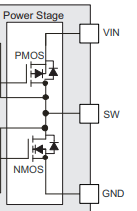
    You can first check the FET resistance and body diode of failure device to see if there's any damage on the High-side FET or Low-side FET.

    SW(+) to VIN(-)  AND  GND(+) to SW(-).

    Also you can check the SW ringing of operating devices to see if it would exceed the spec.

    Athos

  • Hello Athos,

    First of all thank you for your fast reply. I did some tests and measurements on the broken devices, and after ruling out problems with the output MOSFETs, I think I found the cause: the Enable input EN is actively pulled high and low when the device is switched on and off respectively - and this signal should always remain with VIN boundaries.

    However it turns out that under certain power-on and power-off conditions, VIN can unexpectedly become low with EN still high, causing (excess) current to flow into the EN pin, causing a half-short - which is what I found on the failed devices. This also explains why broken devices often still kept working as a regulator.

    The problem may be exacerbated by the VOUT discharge MOSFET being turned on via UVLO with EN still high, causing a rapid pull-down on VIN as well, which may occur when the battery voltage drops below 3 volts.

    Edit: This scenario can't happen, as UVLO automatically turns off the P-MOSFET.

    Luckily, the problem is easily remedied by tying the EN pin to VIN - a built-in Remote Enable feature of the product is never actually used, so the Enable circuitry may be safely bypassed.

    Thank you again for your fast assistance. It may not have brought the solution itself, but it certainly helped me to investigate things in an orderly manner and locate the cause of the problem.

    Regards,

    Richard