
- Ask a related questionWhat is a related question?A related question is a question created from another question. When the related question is created, it will be automatically linked to the original question.
Hi
The customer design with BQ76952, It appears that the GS pin of the pre-discharge MOS of some machines will have a voltage of 1.5V when pre-discharge is not performed, causing the pre-discharge MOS to turn on.
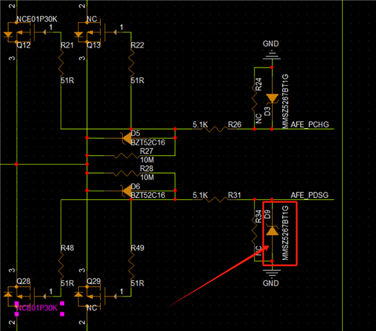
Remove the zener diode in the red mark form the above picture and it will return to normal (after removal, welding the removed zener diode back will also return to normal).
It is judged that the reverse leakage current of the zener diode slowly increases during use. It becomes larger and causes this situation to occur (use a multimeter to test the Zener diode and it is normal and not damaged);
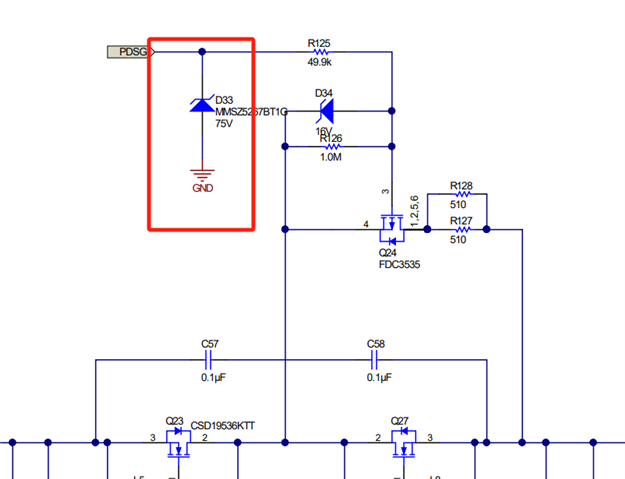
I would like to know the function of the diode in the red mark, can they be removed?
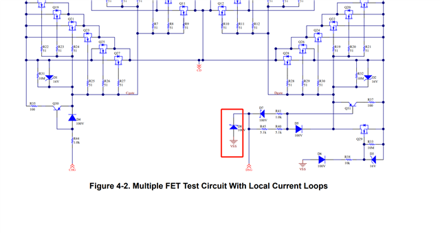
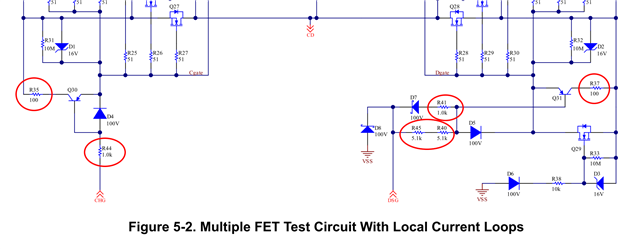
Another question, how to set the resistance of the components marked in the screenshot?
Waiting for your reply.
Thanks
Star


