A related question is a question created from another question. When the related question is created, it will be automatically linked to the original question.
If you have a related question, please click the "Ask a related question" button in the top right corner. The newly created question will be automatically linked to this question.
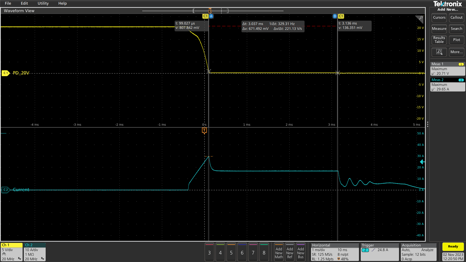
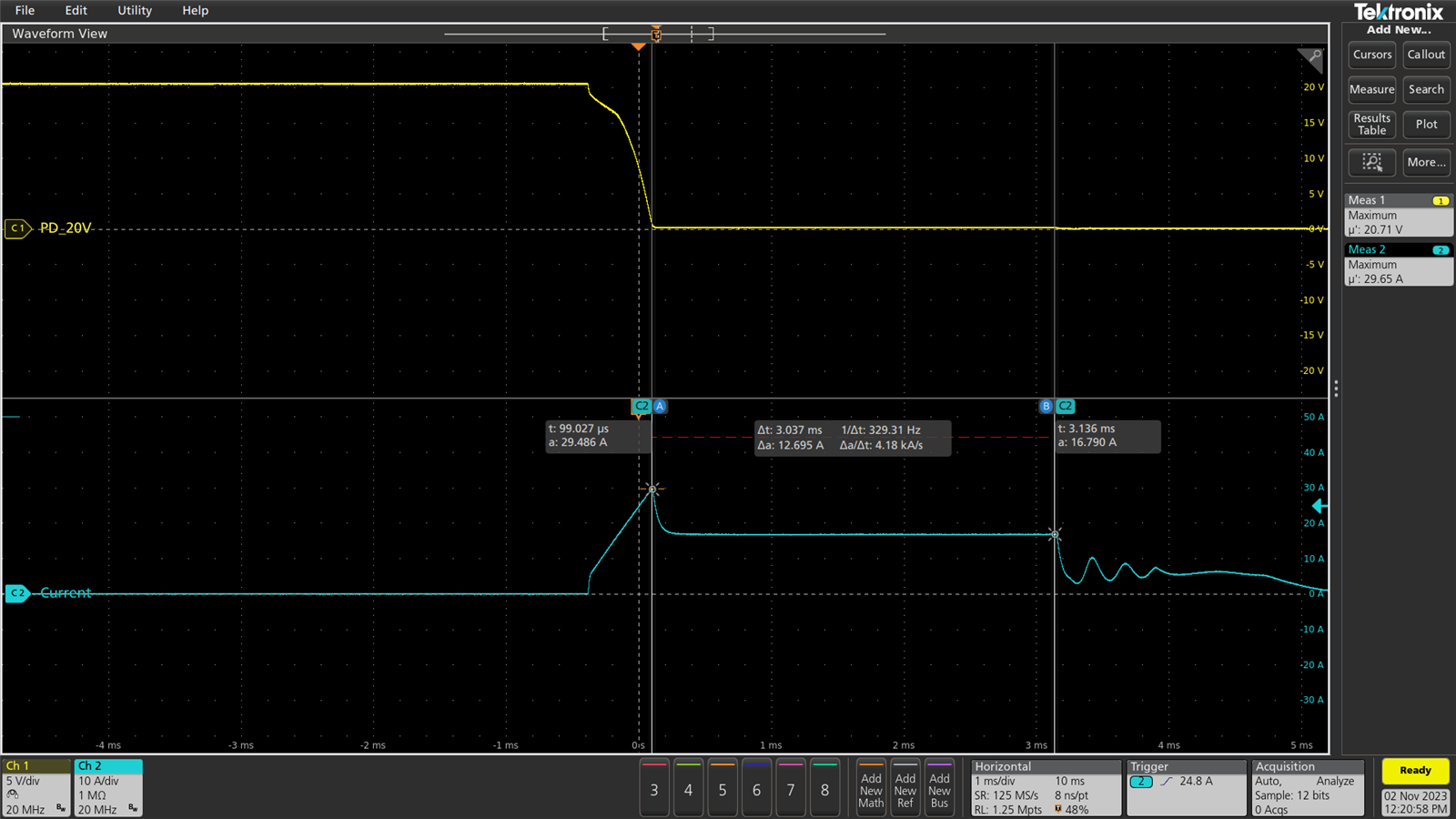
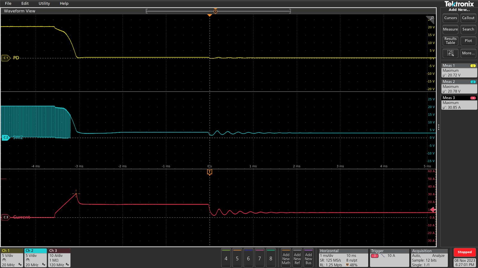
Thanks for the background, may I know if the current is the inductor current?
What is the input voltage and the output current when do the Vout short to GND test?
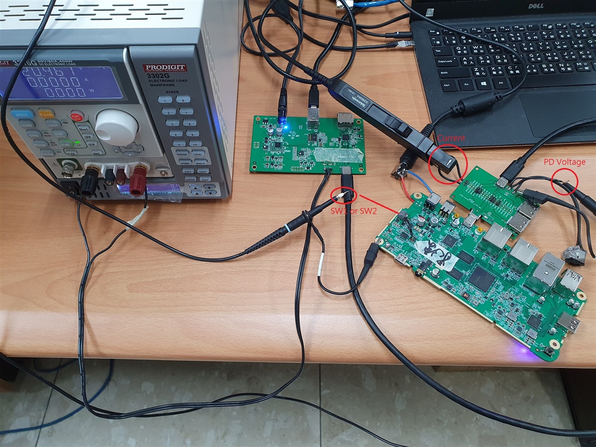
And how does the customer do the short test? Use a air-switch or e-load?
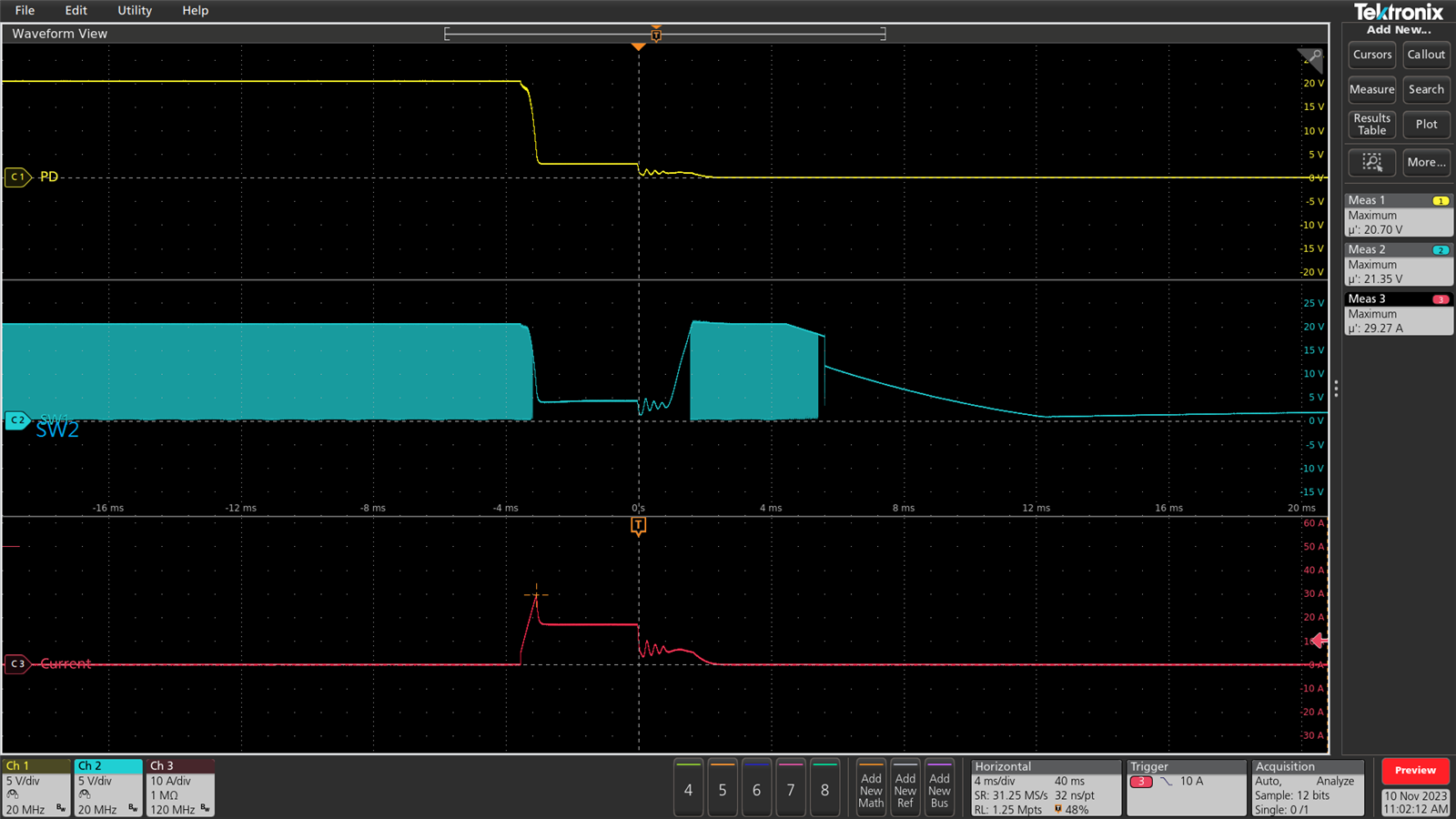
Does the customer test on TI EVM? Because I saw the current uses about 500us to rise to 30A. Can the customer also probe SW1 and SW2 waveforms when doing the test?
1. may I know if the current is the inductor current?
=> output current
2. What is the input voltage and the output current when do the Vout short to GND test?
=> input voltage= 20V, output current = as previous waveform.
3.And how does the customer do the short test? Use a air-switch or e-load?
=> e-load
4. Does the customer test on TI EVM? Because I saw the current uses about 500us to rise to 30A. Can the customer also probe SW1 and SW2 waveforms when doing the test?
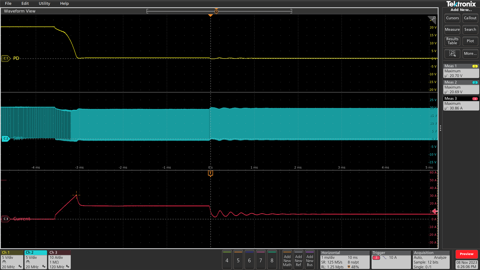
I will do the test with TI EVM on lab together, it is strange that when PD voltage is zero but SW2 still remains 4V, is there is a long wire between Vout and PD? Can you share the schematic and layout for the customer's board?
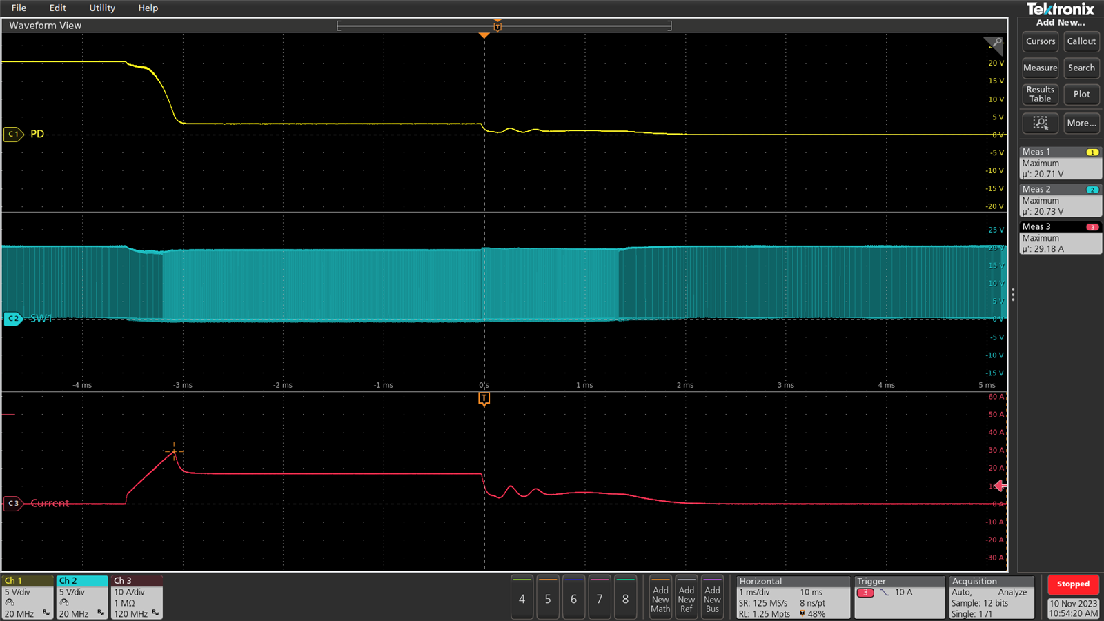
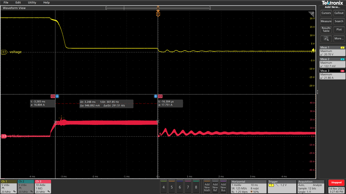
Below is the test result of Vout short to GND on TI EVM, you can see that the max output current is clamped to about 16A which is the average inductor current value.
Can you also share the schematic and layout screenshot?
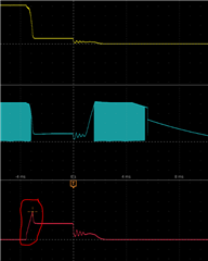
And can you help probe the inductor current when the output current rises to 30A?
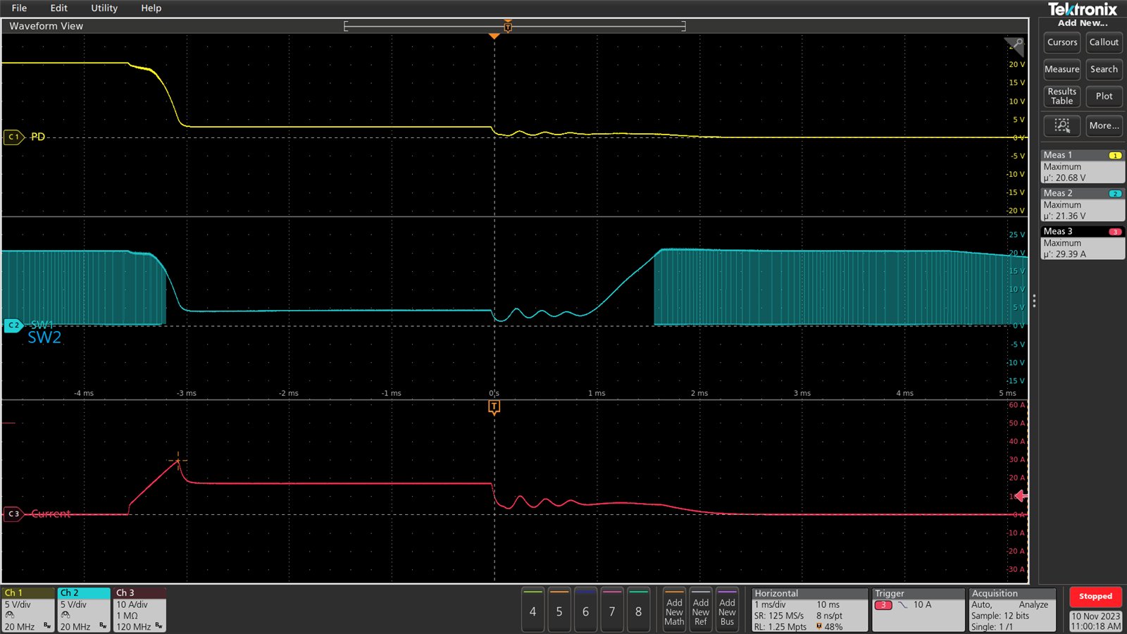
Can you also zoom in the waveform including SW1, SW2, iL, Vout when PD=0 but SW2 is switching? That is strange that PD=0 but SW2 still equals to 20V. Which test point does thecustomer probe at? Can you take a photo and show the test point?
Is there any more feedback from the customer about this? For TPS55288, the inductor current is well limited as set, and looks ok. Recommend to enable the output current and change the ILIM resistor to 40k to set lower average inductor current limit value.
The "OCP Delay" section has three time settings: 3ms, 6ms, and 12ms. I would like to inquire whether, during these time intervals of 3ms, 6ms, and 12ms, there is a specified threshold for the current peak that must be exceeded to trigger Overcurrent Protection (OCP). Alternatively, does OCP remain inactive within these timeframes, regardless of the magnitude of the current peak?
During the delay time intervals of 3ms/6ms/12ms, the output current limit protection is inactive and will not be triggered, but the average inductor current limit is still active.