This thread has been locked.

If you have a related question, please click the "Ask a related question" button in the top right corner. The newly created question will be automatically linked to this question.

LM51551-Q1: Boost converter stops working with load around 100W

Part Number: LM51551-Q1
Other Parts Discussed in Thread: LM5155, LM5121

Hi,

I am designing a 200W boost converter from 12/24V to 50V. Most of the time, the converter will operate around 60W, but sometimes it will need to provide 150-170W for several minutes. I have designed a PCB with LM51551-Q1 (P/N: LM51551QDSSRQ1), schematics attached. I've used both Webench and PSpice for TI for the simulations, both showing perfect startup with 12.5, 25 and 50 Ohm loads. I've also used LM5155 Boost Controller Design Tool spreadsheet.

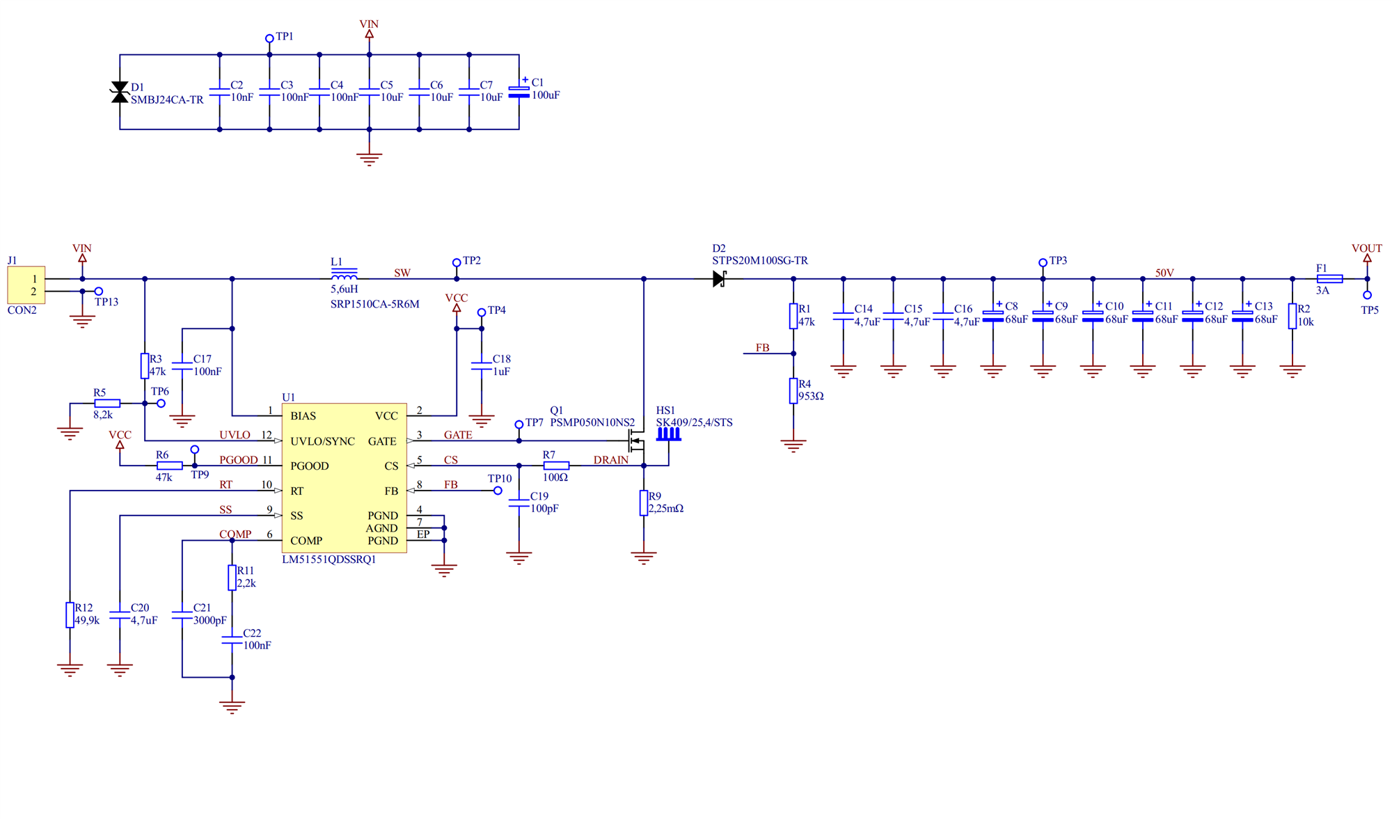
During testing I experienced several problems with startup on 12V - I managed to fix it by changing soft-start capacitor (C20) to 4,7uF. The converter operates smoothly with 50 Ohm load, however when I attach another 50 Ohm resistor in parallel (creating 25 Ohm resistor) PGOOD goes low and the converter stops working - it look like it detects overcurrent, however I am quite far away from the designed current limits. Is anyone able to help me?

Greetings,

Bart

  • Hi Bart,

    Thanks for reaching out and for the detailed description of the situation. 
    Are you connecting the second 50 Ohm resistor during operation (therefore creating a load step) or before you start operating the system?

    Thank you and best regards,
    Bryan

  • Hi Bryan,

    I've tested both. Starting with 25 Ohm causes PGOOD to never reach logic 1, connecting another 50 Ohm resistor parallel while working with 50 Ohm load causes PGOOD to go low right after connecting load.

    Bart

  • Hi Bart,

    Thanks!
    I suspect that the phase margin of the system is on the low side, could you help me understand based on which parameters you designed your compensation circuit?

    If you did it based on the quick start calculator, feel free to send me the excel file, since I'd choose some different values as I see it now. 

    If you happen to have any oscilloscope measurements saved with input/output voltage, switch node voltage and output current, I'd like to take a look at those as well.

    Thank you and best regards,
    Bryan

  • Hi Bryan,

    thanks for your engagement in the case. I am sending you the Excel file I used for calculations, I'll provide oscillograms later (without current, I don't have current probe).

    Bart

    LM5155_Design_V1_1_1.xlsx

  • Hi Bryan,

    I have submitted your previous answer as resolving my issue by mistake. Please find a bunch of oscillograms attached. Going by filenames:

    7 - startup, 10K load

    8 - working, 10K load

    9 - startup, 50 ohm load

    10 - working, 50 ohm load

    11 - startup, 25 ohm load (closeup)

    12 - startup, 25 ohm load

    If you need anything else, do not hesitate to ask.

    Bart

    lm51551_osc.zip

  • Hi Bart,

    No problem at all, I'll keep the thread open.
    Thanks for the files, I'll get back to you once I have an idea on how to solve the issues you're experiencing.

    Thank you and best regards,
    Bryan

  • Hi Bryan,

    have you had a chance to take a peek at the spreadsheet?

    I am analyzing the loop compensation part and comparing it to both my knowledge and articles found in the internet - I am worried about suggested maximum bandwidth in the spreadsheet, it's only 2,8 kHz, where all the articles suggest to keep it in the range of Fsw/10 - Fsw/5 (~44 - ~88 kHz). Why is this bandwidth difference so huge? I am also worried about the gain margin with selected components - it is only -6dB, while should be around -10dB. Do you think that changing Chf to a higher value (e.g. 4700pF) is a good starting point for testing?

    Bart

  • Hi Bart,

    Excuse me for the late response. 
    I'll start by explaining the suggested bandwidth. There a different ways of determining the BW, one of them is the rule of thumb you mentioned of approximately Fsw/10 to Fsw/5. Another method is to base it on the gain-bandwidth-product of the error amplifier that's present within the IC.

    I'll follow this up internally and I'll get back to you today with feedback, also about your first question.

    Thank you and best regards,
    Bryan

  • Hi Bart,

    The bandwidth is changed based on the right-half-plane (RHP) zero, a zero that ever present in the control loops of boost converters.
    The RHP zero frequency is located at 0.5*pi*Rout/L. Another rule of thumb to determine the bandwidth is the RHP-zero frequency divided by three. I believe this is the way chosen in the Quickstart Calculator. Please try tuning your compensation circuit and look if the problems persist with 25 Ohm load.

    Thank you and best regards,
    Bryan

  • Hi Bryan,

    thanks for your response. I assume that the correct equation is 0,5 * PI * Rout / sqrt(L) - am I right? So what is the best approach now? Changing maximum output current to 2 amps to match 25 ohm load and adjust compensation circuit according to the newly calculated values?

    Bart

  • Hi Bart,

    Excuse me for the wrong equation. It should be 0.5 * Rout / (pi * L).
    You could indeed use your proposed approach. Keep in mind that the tuning of a control loop can only be approximated in theory and should finally be done in a lab, since parasitics and uncertainties arising from component placement and PCB routing can only be assessed with a physical board.

    Thank you and best regards,
    Bryan

  • Hi Bryan,

    I did a lot of testing with different compensation circuits and never achieved my goal, so I decided to lower a bit my requirements and designed converter using LM5121.

    Thank you for all your support, really appreciate it.

    Greetings,

    Bart