This thread has been locked.

If you have a related question, please click the "Ask a related question" button in the top right corner. The newly created question will be automatically linked to this question.

LM5069: Circuit goes into current limiting at a level lower than the design expects

Part Number: LM5069

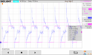
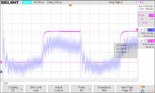
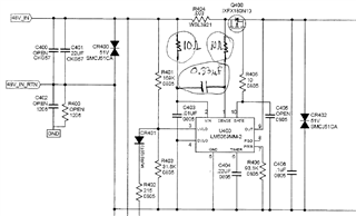
I am using the LM5069 to turn on and off 48V power to an H-bridge motor controller. The motor is not activated until the output is fully up. An LC filter is placed between the output of the FET controlled by the LM5069 and the H-Bridge. When operating the motor, I find that the LM5069 goes into current limiting with positive peak currents of about 11A while the current limit is set for 18.3A. Taking tolerances into consideration, the lowest the current limit should be 16A. The current passing out of the FET also goes negative at points through the motor switching cycle. It gets up to -5A at times. I suspect this is due to the LC filter. Could this negative current be affecting the current limiting level of the LM5069? 

  • It seems that the issue is coming from the current sense layout. The recommended layout is shown below.

    Could you please measure the differential voltage drop across VIN and SENSE pins using a multimeter while 10 A load current is applied?

  • Thanks. I fed 10.25A through the sense resistor and measured 30.3mV between pins 1 & 2 of the LM5069. I am using a single 3 milliohm, 1% tolerance sense resistor with the IC.

    Also, I checked the threshold for current limiting of the IC and found that it measured 17A when I slowly increase the current to where the IC limits. On the other hand, I find that if I pulse the output between 0A and a positive 14.5A at a 25kHz rate, the IC goes into current limiting. Why do you think there would be this difference? Note that I can pulse the output between 0 and 13.4A at a 25kHz rate and the output does not limit.

    Also, do you think that any portion of a pulsed current that goes negative will have a detrimental effect on the operation of the LM5069? 

  • Please perform this test using a DC electronic load or rheostat (not the motor load).

    1. Apply 10 A to 17 A load in your board with a step of 1 A.
    2. Measure the VIN (PIN-2) to SENSE (PIN-1) voltage at the device pin (nowhere else) using a three and half digit digital multimeter.
    3. Measure the current using another digital multimeter accurately and share that data. 
    4. Fill-up this table and share.

    IIN (A)

    VIN_K to SENSE voltage (mV)

    10


    11


    12


    13


    14


    15


    16


    17


  • Avishek,

    This is Lee Mylin, the originating requestor of the help from the forum. Tom D'Auria is a colleague who got me on the forum before I was able to log onto it.

    Here is the data you requested:

    IIN(A)                           VIN_K to SENSE voltage (mV)         Calculated VIN_K to SENSE voltage (mV)

    10.1                             30.3                                                     30.3

    11.0                             33.0                                                     33.0

    11.9                             35.7                                                     35.7

    12.8                             38.5                                                     38.4

    13.8                             41.3                                                     41.4

    15.0                             45.0                                                     45.0

    For some reason the circuit is now limiting between 15 & 16A so we cannot obtain data for larger currents. These results are identical or very close to calculated values, so I believe that there is some other explanation.

    I believe that our problem is voltage spikes on the sense voltage waveform that occur at the transitions of the current pulses. See the following oscilloscope traces. Channel 1 is the Vin to Vsense voltage fed to the LM5069 and Channel 4 is the current flowing through the sense resistor.

    We have a 0.1uF bypass cap at the output of the LM5069 and the load capacitance of 1500uF is located about 4 inches downstream from the LM5069. We had tried increasing the local LM5069 output capacitance to 22uF, but the circuit still limited at just under 15A. The only difference noted was that it now took longer for the timing cap to charge to 4V and current limit the LM5069 than it did without the extra 22uF.

    So we tried to filter the spikes out of the signal fed between Vin an Vsense in the LM5069. We cut the sense lines between it and the sense resistor on our PCB and inserted a 10 ohm resistor in each line. Then we inserted a 0.33uF capacitor across the Vin and Vsense inputs of the IC. This removed the spikes from the Vin to Vsense inputs of the IC and caused our current limit to increase to acceptable limits. See filtered signal in plot below.

    Below is a schematic of the filter we added.

    Although we obtained beneficial results, is this type of filter configuration compatible with the current sense amplifier in the LM5069?

    Please let us know. Thanks.

  • Hi Lee,

    Thanks for your detail explanation. Placing a RC filter is recommended across the current sense resistors to filter out the noise from the sense pin. Please remove the resistance from the VIN path. The resistance only on the SENSE path and the ceramic capacitor are fine in implementing a first order RC filter across the sense resistance. 

  • Thank you Avishek. We modified our filter according to your direction and have obtained acceptable results. 

  • This satisfies our question. Thanks for the help.

  • Glad to know that your problem got resolved. Thanks for your patience.