This thread has been locked.

If you have a related question, please click the "Ask a related question" button in the top right corner. The newly created question will be automatically linked to this question.

LM74720-Q1: Using OVP function & reduce dark current

Part Number: LM74720-Q1
Other Parts Discussed in Thread: LM74722-Q1

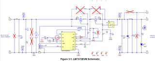
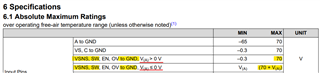
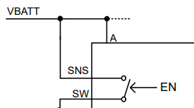
LM74720-Q1/LM74722-Q1"Programming Overvoltage Threshold and Battery Sensing, according to EVM BOARD R14 and R15, when connected to VIN during shutdown, may result increase in standby current, with the specification requiring standby current(Dark current) to be less than 120K.

1.Is it possible to connect a 1M resistor in series to VIN between BATT_MON to reduce dark current?

2.Is it recommended to connect it to the vehicle's IGN/ACC pin for overvoltage protection detection?"

3.Choose not to use the OVP function and not install the resistor? 

4.Choose not to use the OVP function but install resistor

  • Hi Adam,

    Thanks for reaching out to us. Let me get back to you with comment by end of today.

  • Hi Adam,

    1. Ideally we would like to have  the total resistance between Vin and GND which is R14+R15+R16 to be less than 120 kΩ to ensure the current flowing in the path is 100x the 1uA which is the current flowing into the OV pin for its operation. You may consider increasing the total resistance to  1.2 MΩ so that there is at least 10x 1uA current flowing in the path. Using R14+R15+R16 > 1.2MΩ may effect the OV functionality of the IC.  

    2. Yes, you can connect 1MΩ  in series to VIN between BATT_MON  as long as the total resistance between VIN--VSNS--SW--GND  is < 1.2MΩ. 

    3. If OV function is not used, connect the OV pin to GND. If the internal disconnect switch between VSNS and SW is not used, then short them together and connect to C pin.

    4. The internal resistor between SNS and SW can still be used even if OV pin is not used.