This thread has been locked.

If you have a related question, please click the "Ask a related question" button in the top right corner. The newly created question will be automatically linked to this question.

TPS40210: Does Rg is means external gate resistor and MOEFET internal Gate resistor

Part Number: TPS40210

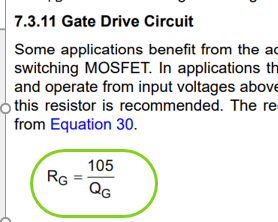
I am curious the vaule of Rg in theTPS40210 DS " Equation 30, Rg= 105/Qg"

Does Rg is Eq30 is means  external gate resistor  and  MOEFET internal Gate resistor 

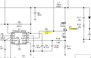
we see the design on TPS40210EVM     

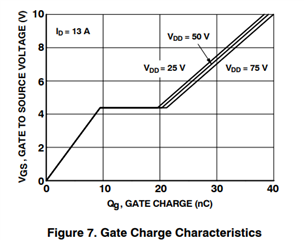
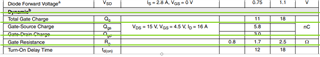
the Qg of the mosfet Q1  is 18 nC

       then Equation 30, Rg= 105/Qg -->105/18 =5.8

But the external Resistor is only 3.3,  

when I add the valute of Rg of Q1 (2.5 ohm,) with the external Resistor  -->3.3+2.5 =5.8 ,

than I can get  "Equation 30, Rg= 105/Qg "  -->105/18= 5.8 is equal to (3.3 + 2.5)

Can you help to confirm the value of Rg in " Equation 30 "(Rg= 105/Qg)  is means  external gate resistor  and Rg of Q1 (MOEFET internal Gate resistor )

thank you

  • Hi Dimitry,

    Thanks for reaching out. I see you've made a new thread, so I went ahead and closed the other one.
    After taking a look at the datasheet of the FET, I can confirm that your calculations are correct. 

    The gate resistance in the datasheet is composed of the bond wires and the pins of the package going to the gate. So it indeed has to be added to the external resistor which connects the IC to the MOSFET.

    Thank you and best regards,
    Bryan

  • HI Bryan

    can you help to recommand how to select right value of Q1 for EQ30 

    the Q1 in my current design is fdms86101-d

    https://www.onsemi.com/download/data-sheet/pdf/fdms86101-d.pdf

    Does Rgate is 3 ohm?

    and vdd is my design is 12V, does Qg is 33 nC?

    then external resistor is (105/33 ) - 3 = 0

    -->Does that means I can put 0 ohm for external resistor ?

    thank you

  • Hi Dimitry,

    It does indeed seem that for the MOSFET you've selected the internal gate resistance is maximum 3 Ohm.
    The total gate charge of said transistor however depends on the voltages which are applied to it.

    Could you tell me more about your circuit requirements? Input and output voltages, desired output current and such parameters.
    In this way we can determine the voltages that would arise at the switch node.

    Thank you and best regards,
    Bryan

  • Hi Bryan

    It does indeed seem that for the MOSFET you've selected the internal gate resistance is maximum 3 Ohm.
    The total gate charge of said transistor however depends on the voltages which are applied to it.

    Do you means we can't select maxmimum value of internal gate resistor?

    and the total gate chage on the figure 7, when Vgs is 8V ( TPS40210 spec), then Qg is around 33nC

    --> that's why I put this value for Equation 30

    I hope focus on Equation 30 first.

    base on my previous caculation ,-->Does that means I can put 0 ohm for external resistor ?

    if there any particular value you need to know, I can provide it.

    thank you

  • Hi Dimitry,

    Thanks for the feedback, I'll get back to you soon with some answers.

    Best regards,
    Bryan

  • Hi Dimitry,

    Excuse me for the long response time.

    The internal gate resistance of a MOSFET is a parameter attached to the switch, it therefore can not be changed. 
    You could choose another MOSFET.

    Like I said, the gate charge depends on you circuit. A safe way to approach would be to add some pads in the path to the gate, where you can place a 0 Ohm resistor, and if you need an additional gate resistance, you could still add a resistor there.

    Thank you and best regards,
    Bryan