This thread has been locked.

If you have a related question, please click the "Ask a related question" button in the top right corner. The newly created question will be automatically linked to this question.

REF3425: EN Pin Leakage Current

Part Number: REF3425
Other Parts Discussed in Thread: REF3225

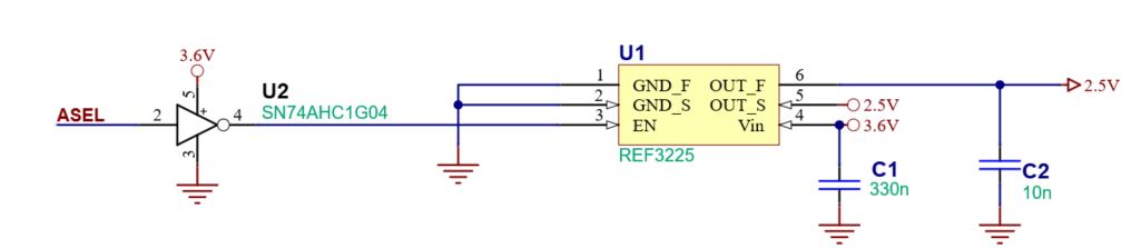
In the datasheet, section 7.5, the ENABLE pin leakage current is specified to be 1-2uA. Does this mean that there is a weak pulldown on the ENABLE pin? We would like to know if this pin can be floating for any length of time during device power up. The circuit where this part is used is referenced below.

https://e2e.ti.com/support/power-management-group/power-management/f/power-management-forum/1285842/ref3225-high-shutdown-current-with-ref3225/4879236#4879236


We are currently using part REF3225 and occasionally see high shutdown current after power up. When testing with a REF3425, we do not see high high shutdown current after power up (same circuit). That datasheet for the REF3225 specifies a ENABLE pin leakage to be much less at only a few nA.

Is there any risk of improper device operation if the ENABLE pin of the REF3425 is floating for some length of time (no more that a few ms) during power up?

  • Hi Jason,

    Thanks for sharing the link to the schematic. 

    We can't guarantee device behavior for voltages on EN outside of these ranges seen in the datasheet:

    This is further explained in section 10.2.2.4 of the REF3425 datasheet:

    What is the power up sequence that you are expecting? You mentioned that the REF3425 is not seeing the same issue as the REF3225 in your circuit. Are you using the same sequence you shared in the previous e2e post you linked here?

    Thanks,

    Jackson

  • Hi Jackson, thank you for the quick reply.

    We are using the exact same sequence that was shared in the previous e2e post. In several cases where we saw high shutdown current using the REF3225 (500uA), we replaced it with the REF3425. Using the REF3425 device we have not seen any issues up to this point (normal shutdown current <2.5uA).

    In the referenced schematic, the signal "ASEL" is driven by a microcontroller which is powered by the same source as the inverting gate U2 (3.6V). During initial power up, the signal "ASEL" is floating and at the same time, U2 may not be at operating voltage yet. It is possible that the ENABLE pin could be within the 0.5V to 1.6V range during that time (several ms). After power up, the voltage on the ENABLE pin is always either low or high (3.6V).

    My question is that once the ENABLE pin falls with in normal logic ranges (less than 0.5V or equal to VIN), shouldn't the REF3425 device then operate normally?

  • Hi Jason,

    On my lab bench, I am not seeing your startup conditions causing issues on my REF3425. I would encourage using REF3425 instead of REF3225. In general, to guarantee correct device operation, I would suggest following the datasheet.

    Thanks,

    Jackson