This thread has been locked.

If you have a related question, please click the "Ask a related question" button in the top right corner. The newly created question will be automatically linked to this question.

BQ25570: BQ25570

Part Number: BQ25570

Good day

We have our own PCB making use of bq25570, I need to get at least 3.3V output with 200mA pulse current.

I did use the calculator and with the component values selected, I can only reach 2.5 V, which is to low to drive the module That I will be using this for.

Trust you could give advice on what I may have missed.

  • Hi Samuel,

    Can you please clarify, you want a 3.3V output from VOUT? 

    Best Regards,

    Juan Ospina

  • Hi

    Yes, I need 3.3V on VOUT, what is the MAX current in this condition.

    300mAh Lithium battery with Supercap

    Solar Input 5V max

    Regards

    Sam

  • Hi Sam,

    The 3.3V on VOUT should be achievable so long as your VBAT_OV is greater than 3.3V. You can use an ROUT1 of 4.75 MOhms and ROUT2 of 8.23 MOhms. What components were limited in your calculations?

    Best Regards,

    Juan Ospina

  • Hi

    Is it critical for the operation of the chip that the resistor networks has to be 13 meg ? I have looked at designs from Mikroe for one of the click boards and it seems that they did not apply that rule, I have managed to get to my required voltage output, but it seems the charging is effected, so I need to know should I change my resistor networks to always have 13 meg overall resistance, will that improve the performance?

    Regards

    Sam

  • HI Sam,

    Yes, it is necessary that resistor based voltage dividers add up to 13 MOhms at most. I'm not familiar with the designs you mention.

    How do you see that your charging is affected in this case? What is your configuration?

    Best Regards,

    Juan Ospina

  • Hi

    This is the link to the product I told you about.

    solar-energy-click-schematic-v100 (mikroe.com)

    I currently have a 20mA load connected to VOUT, but it would seem that the charging is not keeping up with the discharging, I am testing worst case as in practice the load will be around 5uA with a 20mA draw for a couple of seconds(If GPS Fix is slow).

    I could share my schematic, but the one in the link is the same.

    Regards
    Sam

  • Hi Sam,

    The 13 MOhm provides an upper limit for the sum of resistor values for each divider, lower values can be used but they result in worse efficiency due to higher current consumption. The provided schematic has lower total values which will work in order to provide the correct voltage settings, but the current consumption will be greater.

    Can you share information regarding your input source and expected input power at MPPT? The input source can be a limiting factor in terms of charging rate.

    Best Regards,

    Juan Ospina

  • Hi

    The solar input is 5V at 25mA, so I think with a 20mA constant load, it might not get the battery full, but it should at least keep it close to fully charged, but during the night its still draining the battery, so everyday we will start lower.

    Maybe I must use it in the current setup, but use it in the way it will be used and monitor the performance.

    Regards

    Sam

  • HI Sam,

    A constant load of 20 mA may be too significant for your input source parameters if it is limited to some times of the day. It may be sufficient if your load is closer to the 5 uA consumption with periodic 20 mA pulses.

    Best Regards,

    Juan Ospina

  • Hi

    I have now put the TD Next module that I want power via the Solar harvester on a power profiler, Standby current is 26uA , then on TX mode i will use 37mA for 7Seconds and will waiting for a ACK 26mA for 27 seconds, this is repeated at worse case every 15min, only during day time.

    The device resets all the time while connected to the output of the solar harvester, seems like it cannot deliver the output current needed, any suggestions?

    Regards

    Sam

  • Hi Sam,

    The buck output should be able to handle currents up to 110 mA. I have a few questions.

    • What behavior do you see on VOUT in terms of voltage or current?
    • Can you please confirm the VIN, VSTOR, VOUT and VBAT voltages during the transmissions? If possible, a waveform capture of these rails would be helpful.
    • Additionally, what size is your battery? 

    Best Regards,

    Juan Ospina

  • Hi

    Yes I did read that, but under the current test, I have a LED also connected to VOUT, you can actually see the LED dimming very bad and the module restarts itself, so the output should have dropped below 2.2V from 3.6V

    I will see if I can capture this in real-time

    Regards

    Sam

  • Hi

    Readings and info

    300mAh battery

    VOUT not in TX mode, 3.4V when in TX drops to 2.3V(Device Reset)

    VBAT is on 4.089V Stays at that level

    VSTOR 4.071V, does not change during TX

    Hope thats what you needed, I cannot put the device in the sun due to weather conditions

    Regards

    Sam

  • Hi Sam,

    I see, it appears the system load may be pulling more current then the IC can provide in this case, though VBAT and VSTOR don't seem to fall indicating that the power limitations may be across the buck.

    Can you please share your device schematic?

    If the waveforms are available they will still be helpful, additionally, if you can capture the LBUCK waveform to see the switching. These can help give context to what's going on.

    Best Regards,

    Juan Ospina

  • Hi

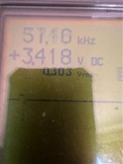
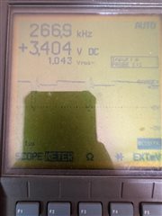
    Checked the frequency at the LBUCK, when the device is in active TX mode the frequency increases to around 230 - 300kHz, when in idle mode I have a refence LED on, it drops to max 30kHz

    I have taken snap shots with my phone, how do I share that with you

    Regards

    Sam

  • Hi Sam,

    Can you share your schematics for this device? It's possible your output voltage is too high for the input voltage and the current you are needing. I'd like to recreate your schematic in lab to confirm the device behavior.

    Best Regards,

    Juan Ospina

  • Solar Harvester.pdfHi

    Sorry for my delayed reply

    Attached the schematic and also the device I am using it with

    Regards

    Sam

  • Hi Sam,

    Based on your schematic the VOUT voltage is meant to be regulated to 1.95V (VBIAS * ((Rout2 + Rout1) / Rout1). or (1.2V * ((560kOhms + 887kOhms)/887kOhms). As I understand you are aiming VOUT to be 3.3V, this would require your Rout2 to be closer to 1.6 MOhms.

    Additionally your BAT_OK voltage seems very low (about 1.55V) which would represent a significantly discharged Lithium battery. 

    Best Regards,

    Juan Ospina