Because of the holidays, TI E2E™ design support forum responses will be delayed from Dec. 25 through Jan. 2. Thank you for your patience.

This thread has been locked.

If you have a related question, please click the "Ask a related question" button in the top right corner. The newly created question will be automatically linked to this question.

LP5036: LP5036 problem

Part Number: LP5036

HI engineers:

    I have some problems about  LP5036: 

    While using the LP5036, I noticed that when the input data changes from 0X7F to 0X80, the output PWM duty cycle undergoes a sudden change. I'm concerned that this might be a bug, so I'm hoping you can check and confirm if this issue exists, and provide a solution. My configuration information is: 9Bits, linear adjustment mode. Thank you very much for your help, and I look forward to your response.

    Thanks,

  • Hi Johnsin,

    Sorry for the late reply, I will check on this and get back to you ASAP.

    BR, Jared

  • Hi Johnsin,

    Do you mean that you change the OUT_Color from 0x7F to 0x80 and the output duty cycle will undergoes a sudden change? Or could you please describe in detail which register you changed and then you observed this phenomenon? And one more question, could you please tell me how you configure the device to 9Bits?

    BR, Jared

  •    The LP503x device allows the users to enable or disable the dithering function through the PWM_Dithering_EN register. When enabled (default), the output PWM duty-cycle accuracy is 12 bits. When disabled, the output PWM duty-cycle accuracy is 9 bits. We set PWM_Dithering_EN to 0, then PWM duty-cycle is 9 bits(0x00 ~0x1FF). The PWM duty-step is 1/512 = 0.001953125 ≈ 0.195%. 

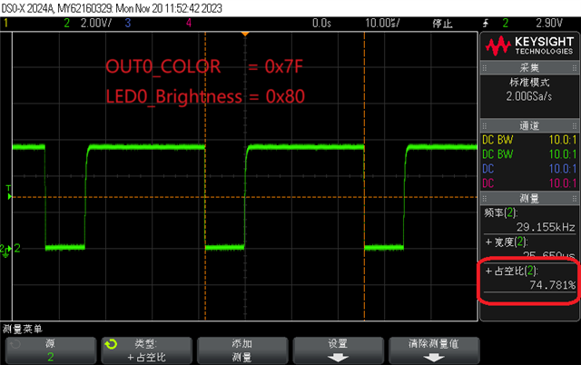
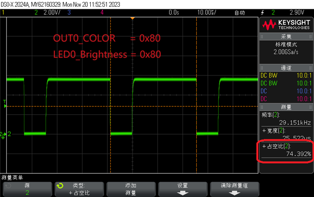
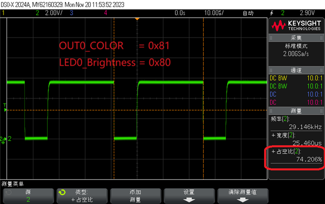
       I set LED0_Brightness register to 0x80 and set  OUT0_COLOR register to 0x7F. The PWM duty on OUT0 is the result of LED0_Brightness * OUT0_COLOR(0x80 * 0x7F = 0x3F80, LP5036 will get MSB 9 bits from 0x3F80 as PWM duty, The duty is 0x7F) according to the datasheet. I use oscilloscope to observe OUT0, then I Get Duty1. After that I set OUT0_COLOR register to 0x80.  I use oscilloscope to observe OUT0, then I Get Duty2. I think Duty2 - Duty1 ≈ 0.195%, but in actual situation Duty2 - Duty1 ≈ 0.4%. This situation is only happened when the value of OUT0_COLOR change from 0x7F to 0x80.

  • Hi Johnsin,

    I will try to do as you comment, please give me some time to do it and I will get back to you ASAP.

    BR, Jared

  • Hi Johnsin,

    I have tested it on the bench and it seems that I can't get the behavior as you said above. Could you please share your waveform and could you please tell me why you concern about this step?

    BR, Jared

  • Please check waveform! 

  • The linearity of PWM duty is very important in our system. 

  • Hi hupfly,

    Thanks for your comments, please give me some time to discuss about this problem with designer. Thanks!

    BR, Jared

  • Hi hupfly,

    Sorry to update late. I have tested this phenomenon on the bench. The reason I didn't observe this behavior before is because the oscilloscope accuracy.

    And I have discussed this problem with our designer, could you please use 12-bit not 9-bit to control the output duty cycle. We think it would be better if you use 12-bit.

    BR, Jared