This thread has been locked.

If you have a related question, please click the "Ask a related question" button in the top right corner. The newly created question will be automatically linked to this question.

TPS25990: Inquiries regarding TPS25990 operation

Part Number: TPS25990
Other Parts Discussed in Thread: TPS25985

Hi, TI support team

1. In order to implement the “Programmable fast overcurrent detect” function described in the datasheet, GPIO3 used as SWEN was changed to Comp1 out, which is the output of Internal Comparator 1. for teeth

I checked by changing the efuse register E4h[2] (Device Config), E2h[7:5], Ebb(comp1 ref)[3:0], and found that once the GPIO3 output goes low, it does not go up again, and the Status Register It was confirmed that the

CMP1_FLT indicator occurs at 80h[0].

Regarding the above, if GPIO3 is not used as SWEN but as Comp1 output, how should the register be set?

(Do I need to save the above settings to NVM and then check it?)

2. An EEPROM is connected to the EVK we are using, but looking at the internal status register value, it appears that both NVMs are used and the EEPROM is not recognized by efuse.

The registered values confirmed for this purpose are E3h[0] = 1 F3h[0] = 1, F3h[7] = 0.

Have you properly checked whether the internal NVM can be used?

Is there anything else I need to check?

If it is true that NVM cannot be used, please tell us what to set up to use an external EEPROM.

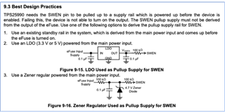
3. Two methods for generating high voltage applied to SWEN of efuse are proposed in the datasheet as shown below.

Is there a reason why the Zener diode voltage was selected as 4.7V?

Is there anything else I need to pay attention to when using Zener diode?
Thanks.

Regards,

MJ

  • Are you using TPS25990EVM?

    If yes, this EVM consists of TPS25900 and TPS25985 in parallel. GPIO3 must be set to SWEN. GPIO2 or GPIO4 should be used as a comparator output. GPIO_CONFIG_12 (E1h, Read/Write Byte) and GPIO_CONFIG_34 (E2h, Read/Write Byte) registers need to be used to configure GPIO2 or GPIO4 as a comparator output. Changing the contents of E1h and E2h registers will be available in the RAM (a volatile memory). Input power recycle or EN recycle makes these registers to reset to their default values. Storing these updated registers content in the NVM will avoid resetting the registers due to input power recycle or EN recycle. But writing into the NVM is only allowed for two (2) times. 

    It seems you might have sent the STORE_USER_ALL (15h, Send Byte) command already two (2) times. Hence, the NVM is exhausted. 

    An external EEPROM is successfully connected by setting the EXT_EEPROM bit high in the DEVICE_CONFIG register. In addition, it is done by configuring two (2) of the four (4) GPIOs as EECLK and EEDATA appropriately in the GPIO_CONFIG_12 and GPIO_CONFIG_34 registers. Make sure those two (2) selected GPIO pins are physically connected to the EEPROM clock and data pins respectively on the board.

    The GPIO3/SWEN pull-up voltage must be within the range of 2.5 V to 5 V.