


Other Parts Discussed in Thread: BQ25756
Hello hope you are doing well,
I have a question about your BQ25750RRVT IC and its development kit BQ25756EVM.
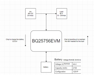
Here is a block diagram of our proposed system.
My questions are;
- Does this application seem alright to you? The bi-directional section of the system will be able to appropriately buck/boost the voltage either way in order to maintain the required voltage and current.
Load: 48V and up to 20 A will need to be supplied from the battery to the load
Charging: 50V and up to 10A will need to be supplied from the DC power supply to the battery (via the chip)
2. As per the block diagram above we plan to use the load on the input side of the charger and the output side of our DC supply to take advantage of the bi-directional charger inorder to discharge the battery with the load. When using your BQ25756-DESIGN-CALC-V01X2 excel spreadsheet are we able to use these calculations with our system layout detailed above as this differs from your recommended layout?
 BQ25756-DESIGN-CALC-V01X2 - THA.xlsx
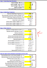
3. I was using the BQ25756-DESIGN-CALC-V01X2 excel spreadsheet. I have inputted my desired value and have received the following ‘red flag’ . It states the minimum inductance. I plan on using an inductor with an inductance value of 3.3 uH as stated. Is this okay or should I look to better spec an inductor (as i need a higher current limit)
4. I also noticed in the datasheet there was a lot of reference to the input voltage being AC EG: Vac and Rac. I just wanted to check that we are able to use this IC and its Devkit with a DC input voltage.
5. The evaluation kit states “The BQ25756EVM has a max input and output of 55 V and a max charge current of 10 A”.
We plan on swapping out the current inductor which is only rated for 16.5 A “IHLP6767GZER100M01” with the following inductor “IHLP6767GZER3R3M11” which is rated for 30A. Does this seem okay with you electrically and footprint wise?
|
IHLP6767GZER100M01 (orignial) |
IHLP6767GZER4R7M11 (Proposed) |
|
|
Current rating (A) |
16.5 |
30 |
|
Inductance (uH) |
10 |
4.7 |
|
Frequency - Self Resonant (MHz) |
9 (from graph) |
10.7 |
*Footprints are matching both “ER” series”
Also, are there any other components/PCB changes which will need to be switched out for the higher current needs. The FET’s and passives seem fine on our end.
Thank you. Hope you have a good day.
