A related question is a question created from another question. When the related question is created, it will be automatically linked to the original question.
If you have a related question, please click the "Ask a related question" button in the top right corner. The newly created question will be automatically linked to this question.
UCC28070: Strange Current Waveforms while using UCC28070
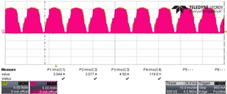
The red waveform (with yellow trace behind it) looks mostly normal, but with some distortion shown by the envelope. This is mainly due to discontinuous current in the boost inductors. At the line and load conditions at which you captured these waveforms there is no CCM in the inductors, only DCM and that results in the distortion.
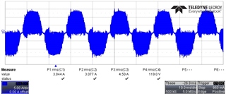
If the blue waveform truly is the AC-line input current, then it shows all switching. That means that you have no Cin capacitor after the diode bridge and no EMI filter before the diode bridge. All inductor switching currents are being drawn straight from the AC-line.
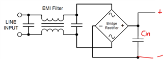
I looked through the UCC28070 datasheet to find an example diagram of these components and I am surprised to find none. All of the system level schematic diagrams have these components removed to simplify the diagrams to focus on the controller components. But Cin and the EMI filter are still necessary components of a real PFC converter. I've copied a snippet from the UCC28180 PFC application diagram to show these parts:
Apparently, the author of the UCC28070 datasheet made all of the schematics a little bit too simple and assumed that "everybody knows" that those components are part of the design. Please note that even the EMI filter structure shown may be too simple for very high power levels. Also note that the UCC28070 does not address the design procedure for these components, but the UCC28180 datasheet does have equations for finding the value of Cin on page 26 of its datasheet: https://www.ti.com/lit/gpn/ucc28180