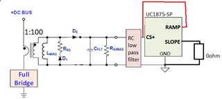
I am designing a PSFB converter using the UC1875-SP. I would like to configure it for peak current mode control with slope compensation. Note that I am using a 1:100 current sense transformer circuit at the input to sense the input current telemetry.
To achieve CMC with Slope Comp, the datasheet recommends the following about the Slope pin and Ramp pin:
"For current-mode control the ramp generator may be disabled by (1) grounding the slope pin and (2) using the ramp pin
as a direct current sense input to the PWM comparator."
Please confirm if I have understood this correctly:
For (1), tie SLOPE pin to Ground using a 0ohm resistor. This disables the ramp generator.
For (2), tie the input current sense signal to the RAMP pin. Can this signal be the same input current sense signal that is fed into the CS+ pin (illustration below, red wire)? 
-
Ask a related question
What is a related question?A related question is a question created from another question. When the related question is created, it will be automatically linked to the original question.


