Other Parts Discussed in Thread: LM5148,
Hi, dear TI team
I’m using a digital potential meter as the feedback resistor to control the Vout of LM5117 buck. Vin = 48V. f_sw = 185 kHz.
- When there is no load, Vout=32V is correct. C38 (capacitor at SS) is very hot when no load, about 80 degrees.
- When connect to a load (48Ohm, should draw 0.6A). Vout is immediately drops to 0V, and no current output. C38 (capacitor at SS) is less hot with load (but no current), about 50 degrees.

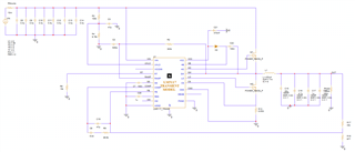
Webench simulation circuit

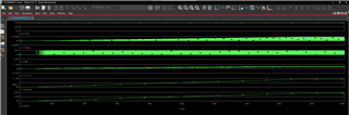
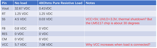
Below are the measurements:
Vout, RT, SS, FB, RES, CM. VCC
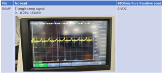
RAMP
COMP

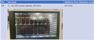
HB
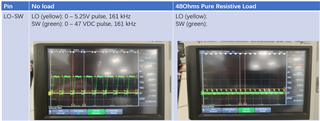
HO - SW
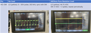
LO - SW