A related question is a question created from another question. When the related question is created, it will be automatically linked to the original question.
If you have a related question, please click the "Ask a related question" button in the top right corner. The newly created question will be automatically linked to this question.
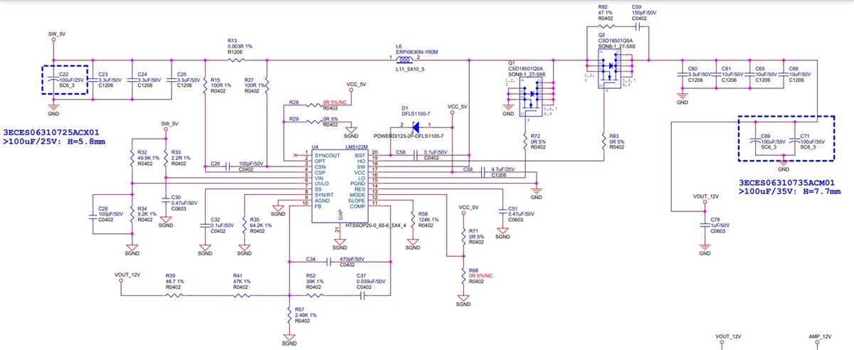
Thanks for reaching out. The connections are placed correctly. I hope you have used the proposed calculation from the datasheet to assure plenty of phase margin for the compensation loop.
But in the datasheet the output voltage level is set by the following equation: Rfb2/Rfb1 = Vout/1.2V - 1. Thus, the ratio between the resistor should be 9 if I'm not mistaken, but I get the value of 18.9 when I calculate it using your chosen resistors.
Please look into this. If the resistor values have to be changed, this would also change your crossover frequency, feedback DC gain and more, thus requiring a second look at the compensation circuit.