This thread has been locked.

If you have a related question, please click the "Ask a related question" button in the top right corner. The newly created question will be automatically linked to this question.

LM5023: PWM comparator operating principle

Part Number: LM5023
Other Parts Discussed in Thread: TL431

Hello.


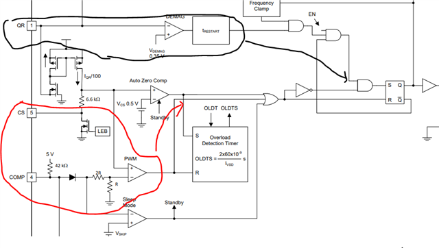
I have a question about the driving principle of the PWM comparator in the datasheet block diagram during Flyback design using LM5023.

1. Could you tell me how to turn PWM ON and OFF?

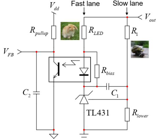
2. In the circuit constructed using the photocoupler and TL431, the COMP pin voltage appears to be DC except for the peak that appears to be switching noise. Why is this?

please answer about my question.


thank you

  • Hi Mr. Kang,

    Thank you for the query on LM5023.

    The LM5023 turns on in QR mode when the voltage across switch is close to valley by monitoring the aux winding. (shown in black below) and turn off happens at the pak of inductor current with reference coming from the output of compensator (red block below). Each of these goes to the S &R inputs and initiates the PWM process. Yes COMP appear DC wth switching noise, it is recommended to keep capacitance as close as possible here to filter this noise.

    Regards,

    Harish

  • Hello Harish.

    Thank you for you kind reply.

    Could i ask one more question?

    1. Assuming that the QR pin voltage and QR delay are the same, is the QR current proportional to the COMP voltage?

    (Comp voltage increases when QR pin current increases, COMP voltage decreases when QR pin current decreases)

    2. If yes, if the QR pin current increases and the COMP voltage increases, does the switching frequency decrease and the duty increase?

    (If the QR pin current decreases and the COMP pin voltage decreases, does the switching frequency increase and the duty decrease?)

    Thank you for always kind answers.

    Have a nice weekend.

    Thank you

  • Hi Mr. Kang,

    Thank you for the reply.

    The variation in load power (COMP) with respect to frequency is shown below. So when the controller operating at the constant frequency region 130khz, the current will be amplitude modulated to vary output power. Now as the load is further increased, increase in current is compensated by reduction in frequency to meet load demand and meet efficiency requirements.

    Please let us know if you have further questions.

    Regards,

    Harish

  • Hello Harish.

    Thank you for your kind reply Slight smile

    I fixed the QR pin voltage and delay. And I increased the QR current by changing the QR pin resistance.

    As a result, the COMP voltage increased and the switching frequency decreased.
    (input and load are the same)


    Does this mean that as the QR current increases, Vcs increases, causing the controller to operate at a higher load range?

    And could you explain why the COMP voltage appears to be DC?

    Thank you

  • Hi Mr. Kang,

    Thank you for reaching out.

    The COMP pin appears to be DC. The following image taken from C Basso's note:

    When the power supply regulates at the correct level, at the exact regulation point and you measure the voltage across Rlowermust be around 2.5V. At power-up, the output voltage is 0 V and the TL431 is inactive. Because there is no current in the LED, there is no drop across Rled and the voltage at the TL431 cathode is Vout-Vf, where Vf is the LED voltage drop ~1V.  When the output voltage increases cycle-by-cycle, at some point, the TL431 wakes up because there is enough voltage to supply the internal circuitry and ensure the 2.5-V reference voltage (around 2.5-3 V on the cathode). As Vout is still far from the target, the voltage at the REF pin is low because of the divider made of : the TL431 remains in a high-impedance state and the voltage across C2 in the primary side is maximum (5 V perhaps depending on the IC), asking for the maximum peak current. Before Vout reaches the target value, the voltage at the REF pin approaches 2.5 V and the TL431 starts sinking current: the voltage at the opto collector begins to fall, reducing the peak current setpoint. If the loop is well stabilized, the TL431 will sink enough current to maintain, via the LED current, a certain voltage on the collector which, in turn, imposes the correct operating peak current in the circuit for the input and output conditions: the loop is closed and the converter regulates nicely. If Vout drops because more current is absorbed from the load, the TL431 will sink less current and the opto collector voltage will rise, asking for more peak. if Vout increases because the converter enters light-load conditions, more current flows in the LED and the collector voltage drops until the new adequate peak current is obtained. So At any operating point in regulation, the voltage at the TL431 cathode is Vk = Vout-RledIf-Vf. It is important to understand that current If which flows in the fast lane, in regulation, solely depends on the primary-side collector current: If = Ic/CTR. So the current in the COMP/ FB pin pin will be a DC value depending on the load conditions.

    When FET Q1 is on the IQR = -Vin*Naux/(Np*R1).  The LM5023 will take the IQR current and divide it by a 100 and output it through the CS pin.  With Rexternal this will level shift the CS trip point with changes in input voltage.

    Regards,

    Harish

  • Hello Harish

    It's late to say thank you.

    Thanks to you, I can now see how the COMP voltage changes.

    Could you explain once again why the frequency changes depending on the load? (Is it related to duty?)

    And in the case of TL431, how does the impedance between the cathode and anode change if it exceeds the reference voltage Min and Max in the data sheet? (Opens immediately? Or does the impedance gradually increase)?

    Thank you as always for answering my long questions.

    Have a nice day!

  • Hi Mr. Kang,

    Thank you for following up.

    The frequency hits 130khz and remains flat (in the amplitude modulation region) where peak current is modulated (duty cycle is changed). As the load is further increased, the peak current is increased (upto the 500mv limit corresponding to max power) with corresponding decrease in switching frequency upto rated power. This is in accordance to control law.

    On how TL431 impedance changes, there is a note in TL431 datasheet (page 20) mentioning about dynamic impedance in the link below.

    https://www.ti.com/lit/ds/symlink/tl431.pdf?ts=1701229077683&ref_url=https%253A%252F%252Fwww.google.com%252F

    I think it would be better to post a separate query regarding this tagging only TL431 as the specific product experts can help clarify on this with greater details.

    Regards,

    Harish

  • Hello Harish

    I don't know how to thank you.

    Your answer was very helpful.

    I will study flyback more.

    Thank you.

    Regards,

    Eunseok,

  • Hi Mr. Kang

    Thank you for the kind words.

    Please feel free to post in this forum for any help on the products.

    Regards,

    Harish