This thread has been locked.

If you have a related question, please click the "Ask a related question" button in the top right corner. The newly created question will be automatically linked to this question.

BQ25120A: Verifying NTC functionality

Part Number: BQ25120A

Hello,

We are using the BQ25120A and would like to enable the NTC functionality to limit charging to our battery.

We would like to set the charging temperature range to be 0 to 45°C.

This means RCOLD should be 0°C and RHOT be 45°C.

We are using an NTC with part number NTCG103JX103DT1:

https://product.tdk.com/en/search/sensor/ntc/chip-ntc-thermistor/info?part_no=NTCG103JX103DT1

At 0 and 45°C, we get the following NTC values according to the RT Sheet of the part number:
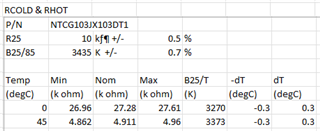
Based on these NTC values and using the TS calculator provided in another thread, we received the following values:
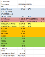
https://e2e.ti.com/support/power-management-group/power-management/f/power-management-forum/534324/bq25120---ntc-resistor-divider-formulas/2325087#2325087

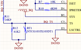
And using the RHI and RLO values calculated, we used the following configuration:
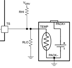
https://www.digikey.com/en/products/detail/te-connectivity-passive-product/CPF0201B41K2E1/14007003

https://www.digikey.com/en/products/detail/te-connectivity-passive-product/CPF0201B24K9E1/14006959

Upon testing, however, our charging current of 24mA is not decreased even all the way up to 60°C.

1) How should we properly configure this resistor network for proper functionality?

2) Are the values I used in the calculator tool incorrect?

3) Is there a firmware setting that needs to be enabled for proper NTC functionality?

4) Is it an issue with the NTC selection?  Does the beta constant need to be increased?  I did see this thread:

https://e2e.ti.com/support/power-management-group/power-management/f/power-management-forum/1290652/bq25120a-ntc-management/4895596?tisearch=e2e-sitesearch&keymatch=bq25120a%20ntc%20beta#4895596


Thank you!

  • Hi Dennis,

    I'll verify your calculated thresholds and get back to you tomorrow.

    With regards to your other questions.

    1. Your resistor configuration is correct and the voltage divider is pulled up to VIN.

    2. This is something I'll verify with the other calculations.

    3. No, the default charger values should allow for proper TS behavior.

    4. The beta of the NTC is fine for a normal configuration but I'll have to double check for the tighter 0-45C constraints.

    As a quick additional question, can you please verify the TS voltage at a few temperature points to verify that we are getting correct voltages?

    Best Regards,

    Juan Ospina

  • Hello Juan,

    Thank you for the follow-up.

    We will make a few voltage measurements to verify the TS voltage at a few temperature points.

    We will provide this information tomorrow.

    Thank you!

  • Hi Dennis,

    Based on the provided configuration and NTC information you provided this should work for a 0-45°C temperature window. I would verify the voltages at different points as mentioned as well as VIN in order to confirm that the voltage at TS is correct.

    Best Regards,

    Juan Ospina

  • Hello Juan,

    Please see the VIN, charging current, and different voltage levels we read:

    https://drive.google.com/file/d/13tWW3h_xtQ66r9c2E-EOL3SjWajzO2ya/view?usp=drive_link

    For the full images and references, please refer to the folder here:

    https://drive.google.com/drive/folders/11HlzD2Dp05vsNT2T58_J1P6BFoeQdzeT?usp=sharing

    Would you be able to review these results and confirm the expected behavior?

    Thank you,

    Dennis

  • Hi Dennis,

    The Measured TS seems to be in the correct area for the temperature values you've provided. I've noticed that for your input voltage there's significant oscillation. Is this expected for your application?

    Can you please share the device register values for when temperature is above 45°C (VTS is below 0.72V)?

    Best Regards,

    Juan Ospina

  • Hello Juan,

    Yes, our system is advertising BLE so we do see peaks of current consumption every few seconds.  This is to be expected.

    When you refer to register values, you are referring to the registers of the BQ25120A, correct?

    Would there be a specific register you would like the values to?

    Thank you,

    Dennis

  • Hi Dennis,

    That's right, the BQ25120A values. I'm particularly interested in REG00, REG01, and REG02

    Best Regards,

    Juan Ospina

  • Hello Juan,

    Thank you for the feedback!

    We will provide you these values tomorrow.

    Thank you,

    Dennis

  • Hello Juan,

    Apologies for the delayed response.

    At room temperature, we were reading the following values:

    REG00: x41

    REG01: x00

    REG02: x08

    We tried raising the temperature all the way up to 53C (660mV), but the register values did not change.

    Would you be able to provide insight into this?

    Thank you,

    Dennis

  • Hi Dennis, 

    Based on REG02 at 0x08, it looks like TS Function might be disabled. It can be enabled by setting Bit 7 of REG02.

    Best Regards,

    Juan Ospina

  • Hello Juan,

    Thanks so much for the feedback!  This did enable the charging to stop.

    Below is a snapshot of the charging stopping and resuming:

    https://drive.google.com/file/d/1jyKhhmducL2WHONdWdE346JB9MG8AWZM/view?usp=drive_link

    And here is a video of it in action with the temperature probe:

    https://drive.google.com/file/d/1WNjEwBlfYossEpT-oxLN6k47ghUvAlPV/view?usp=drive_link

    We recorded the register values for REG002 under the following conditions:

    x88 at room temperature

    xA8 at around 48C --> would this be V_hot?

    xE8 at around 45C --> would this be V_warm?

    Would you be able to confirm these register values are normal?

    We noticed that the temperature at which charging is stopped and resumed are different.  In our case, the charging stopped at 48C, but the system had to cool all the way down to 45C to resume charging.  Is this to prevent hysteresis?  In which the charging is constantly toggled on and off at one temperature value?

    For our design requirements, we would like charging to be cut at 45C instead of 48C.  We did design the resistor network using 45C as the reference value, it would seem this 45C is for the charging resuming temperature?  How should we set the charging stopping temperature resistor network to be 45C instead?

    Thank you!

    Dennis

  • Hi Dennis,

    Those are correct register values.

    That is right, the voltage for each threshold has a 1% of VIN voltage hysteresis.

    Can you confirm the TS voltage at 48C when the cutoff occurs, and VIN at that time as well. I'd like to confirm the % of VIN at which this happens in order to determine how the resistor network can be adjusted.

    Best Regards,

    Juan Ospina

  • Hello Juan,

    Thank you for the confirmation!

    I noticed the TS voltage was around 760mV at 48C.

    And VIN was around 4.79V at 48C.

    Please advise these measurements were made separately and not from the same continuous reading.

    You may refer to the pictures below:

    https://drive.google.com/drive/folders/1fJrQ62elVDc39zCe6ZNjHTVXpAPjJrA0?usp=drive_link

    I did notice that both TS and VIN seemed to "saturate" and turn into a straight line above 48C.

    And once below 48C, they returned to a more noisy and oscillating waveforms as before.

    Thank you,

    Dennis

  • Hi Dennis,

    The oscillation vs "saturation" may be the result of charging starting and ending, as in your application seems to have some amount of oscillation which will affect the VTS through the voltage divider.

    In order to reduce the cut off rate from 48C to 45C you will have to increase your R1 resistance slightly. Due to tolerances in terms of the IC as well as resistance tolerances an exact value can be difficult to pin down. I would recommend testing a few resistor values up to 26.5kOhms to identify which resistance would work best for your application.

    Changing this resistance may also alter the low-temperature cut-off point so I recommend testing that as well at the resistor values to ensure that also stays within an acceptable range.

    Best Regards,

    Juan Ospina

  • Hello Juan,

    Thank you so much for the feedback!

    Looking at available values, we placed an order for 25.5k, 26.1k, and 26.7k resistors to test.

    Once they arrive, we'll see which value best aligns with the 45C cutoff point.

    Just to make sure - you mentioned increasing the R1 resistance, but you would be referring to R11 in the schematic attached to this original post, correct?

    And this would be RHI, not RLO?

    Thank you,

    Dennis

  • Hi Dennis,

    That's right, I meant R11 in the schematic, RHI.

    Best Regards,

    Juan Ospina