This thread has been locked.

If you have a related question, please click the "Ask a related question" button in the top right corner. The newly created question will be automatically linked to this question.

TPS2553: Inrush current turns off MOSFET for about 4-5ms

Part Number: TPS2553
Other Parts Discussed in Thread: LM5113

Hi together,

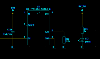
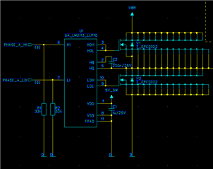
we are using TPS2553 in order to switch the gatedriver suply for three LM5113 with EPC GAN-Fets. We inspected, that the current limit MOSFET of the TPS2553 turns off
when we start sending PWM signals to the gatedrivers (Gatedriver decoupled according to datasheet with 1uF each).

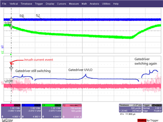
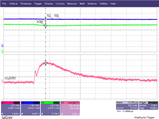
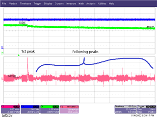
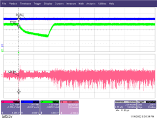
We could measure high inrush currents of about 3A within 300ns. Current limit of the TPS2553 is set to about 250mA, which is more than sufficient at normal operation.

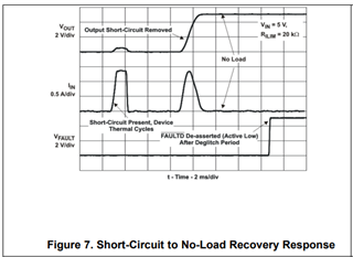
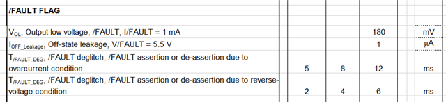
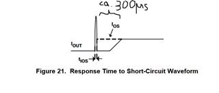
So as I understand from the datasheet, the TPS2553 needs at least 2us to respond to an overcurrent event (our inrush event is way faster than that).
Then it says, that the current limit amplifier recovers after the short circuit event has gone and starts regulating to the current limit set.
In our case, the inrush current sinks within 1us from 3A to values under 250mA.

In an other thread i read, that it takes about 300-500us until the current limit amplifier recovers. We can observe, that in our case it takes 4-5ms and don´t know why?
nFAULT is not triggered. This leads to the problem, that the gatedrivers fall into UVLO and recover after 4-5ms when the current limitation MOSFET decides to turn on again.

It seems like that the high and fast inrush current transient causing the regulator to enter a bad state.
Is there anything known about problems with fast inrush current transients?

Thanks in advance!

  • Hi Karl,

    Based on your description, I think the TPS2553 behavior is probably matched with below short-circuit to No-load recovery response. 3A inrush current would lead to a response for short circuits protection and then it would take several seconds to recovery the faults signal status.

    Is there any chance you could help to share some test waveforms for further analysis, like VOUT, IIN, and Faults pin waveforms?


    Best regards

    Shuai

  • Thanks for your fast response.

    That might be the problem. The current measurements I made was without the TPS2553 in order to place an appropriate shunt resistor to measure the current. Today, I made a new setup with shunt AND TPS2553 to measure the real current drawn even when the IC is mounted. Since it also brings some series resistance of about 85mR into the current path.
    Therefore, the current peak should be lower, but the phenomenon should be the same.
    I try to provide some waveforms tomorrow.

  • Hi Karl,

    Thanks for your kindly clarification and update. Let's see if this problem is a expected one and what we can do to avoid this.

    Best regards

    Shuai

  • Hey Shuai,

    we generated some scope waveforms.
    But first, let me give you some more details about our usage of the TPS2553.
    (V_in=5V, R_ILim=100k, C_in=3uF low impedant, C_out=3uF)
    The TPS2553 is already enabled long time before the problem occurs.

    We used a 5mR shunt resistor at the output to measure the current with a differential high-speed probe.

    C2 red: Input voltage 5VD
    C3 blue: nFAULT
    C4 green: Output voltage 5VSW
    F2 pink: Output current of TPS2553

    We now can observe a about 2.5A fast inrush current event, which brings the TPS2553 to turn off its FET.
    After about 4ms it turns on again by itself. The nFAULT pin stays high all the time.

    As I already mentioned, we have three LM5113 drivers with GAN-Fets behind the switch and the current event happens when we start sending PWM patterns to the gate drivers. In the zoomed-out plot you can even see the PWM pulses from the gate drivers in the current waveform and also observe when 5VSW gets too low and forces the gate drivers to UVLO.

    From my understanding, this is a very fast "No-Load to short-circuit transient response" which overdrives the current-sense amplifier. But then what happens when the current amplifier is overdriven?

    Do you have any meaningful explanation for this? Maybe regarding to chapter 9.3.1 from the datasheet?
    Or any suggestions what we should do?

    Best regards,

    Clemens

  • Hi Clemens,

    Thanks for your kindly sharing for these waveforms and description.

    I will deep dive with the TPS2553 to answer your questions after I research the internal circuits with designer. Thanks for your understanding and patience.

    Best regards

    Shuai

  • Hi Clemens,

    For your question, when the current amplifier is overdriven the driver will switch off the power switch and VOUT will go to discharge. That's the reason why there is a VOUT drop when the overcurrent happens.

    By the way, I have several questions for this case as below descripted, could you please help share more information?

    1. Please help share the schematic of TPS2553, I want to confirm how much output capacitor is used.

    2. Why there is a 250mA current limit setting with TPS2553, as we can see when the PWM signal switching, more than 250mA current is operated. 

    3. Could you please help capture the waveform with longer time which may include the Fault signal recovery time?

    Best regards

    Shuai

  • Hi Shuai,

    thanks for your reply. I try to collect the informations regarding 1. and 2. and do some more measurements for 3. this week.

    About overdriving the amplifier, is there any time we have to wait, when the amplifier is overdriven? So in our case it is about 3.5-4ms.


    I found an other thread where they had similar problems with USB-Loads. Unfortunately, they closed the thread and started further discussing by E-Mail. Maybe you can look it up and see what the problem in that case was?


    https://e2e.ti.com/support/power-management-group/power-management/f/power-management-forum/929429/tps2553-tps2553-voltage-drop-after-the-startup-inrush-current-limit

    Best,

    Clemens

  • Hi Clemens,

    Below are some information for your reference, these data are from silicon Verification and validation compliance matrix. In this case, I think there at least need one turn on time and one turn off time, which total will be 2.9ms

    For the similar E2E thread question, I have confirmed with our team member. The email tracking history wasn't found as it's three years ago and my colleague shared the final solution was to add the OUT capacitor value to defend output voltage drop when the power switch turns off.

    Best regards

    Shuai

  • Hi Shuai,

    regarding your questions, here are some answers:

    1.

    The TPS2553 in our schematic:

    One of three Phases, supplied by the TPS2553:

    So the total output capacity is about 3uF. 1uF at eacht LM5113 gate driver.
    As I also asked in this thread (https://e2e.ti.com/support/power-management-group/power-management/f/power-management-forum/1293710/lm5113-high-inrush-current-transient/4908934#4908934), why the first current pulse is that much intense? Okay, the bootstrap capacitor has to be charged at the first pulse, but there is series resistance which prevents from such sharp current pulses. So to bring it on the point, the two things I am wondering are:
    - What causes such a fast and sharp current pulse (just the first) of the LM5113?
    - Why does that pulse force the TPS2553 to turn off?

    We also increased the "output"-capacity to 6uF. This decreased the current pulse a little, but the TPS2553 turned off anyways.

    From the first point of view, replacing the TPS2553 wit an MIC2019 (same max. current setting) seems to solve the problem.
    It does not turn off. Maybe because it has more series resistance, which forces the Gate-Driver to drain more current from the decoupling capacitor than of the higher impedant path through the switch.

    2.

    The average current is less than the current limit set. Of course there are current peaks at each PWM switching cycle. But the TPS2553 has no problems with the current peaks of the following pulses. Just the heavy first current peak forces the TPS2553 to shut down. And in my opinion, it won´t make sense to set the current limit to the peak value.


    3.

    As you can see, the fault signal stays high for the entire time.

    Best regards,

    Clemens

  • Hi Clemens,

    Thanks for your information and I will look into the waveforms and schematic and then come back to you with update.

    Regards

    Shuai