This thread has been locked.

If you have a related question, please click the "Ask a related question" button in the top right corner. The newly created question will be automatically linked to this question.

LP877451Q1EVM: LP877451 can't work normal

Part Number: LP877451Q1EVM

Dear TI experts,

We encountered a problem when using LP877451. After PCBA was powered on, there was an instantaneous voltage pulse below 3V at the input end of LP877451, and then the input end remained stable at 3.28V.

Enable was also at a high level of 3.23V, and the measured VOUT LDO was 1.8V.

However, nRSTOUT remained low and there were no outputs in several channels.

Please help to see what the problem is,

To exit this state, can I only power on or reset the LP877451 again. Is this the characteristic of LP877451?

Thanks.

  • Hello Zhu,

    I need more clarification to understand the nature of the issue. From the question, you are using EVM board right? what do you mean by PCBA here then?

    If you are using EVM board, then are you giving input supply using 3.3 V input or are you using preregulator on the board using 12 V input supply?

    Can you capture the scope shots of behavior that you are observing and share with us. 

    Best regards,

    Ishtiaque Panhwar

  • Hi,

    PCBA is designed by us.

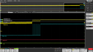
    The following image is the waveform I captured and the corresponding signal is marked on the picture

    PMIC IN---LP877451 Input

    PMIC EN---LP877451 Enable

    NRSOUT---LP877451 nRSTOUT

    1V0---LP877451 BUCK2 output

    Component model:LP877451A1RXVRQ1

    Thanks.

  • Hi, 

    Thanks for sharing the scope shot. 

    So, When the VIN goes to 3 V that means it is hitting UV of VCCA monitoring and that causes PMIC to shutdown. I don't know from what moment does the PMIC VIN goes to 3V. So may be this is caused by pre-regulator. You mentioned that when PCBA is powered on, so do you mean that this is caused during start up or initially it got started and then it went to 3V low level?

    PMIC expects 3.3 V with +/- 8% UV/OV monitoring window. The input to the PMIC should be within that range. Please debug why the input is not stable and if possible you can share the schematic of your board. Thanks

    Best regards,

    Ishtiaque Panhwar 

  • Hi,

    The problem occurred during the startup process,and the following is our schematic. Please help check if there are any issues.


    Whether the input UV detection of PMIC can be turned off?

    Can the shutdown triggered by UV detection at the input of PMIC only be restored by re powering on or resetting?

    Thanks.

  • Hello Zhu,

    Thanks for sharing the schematics. 

    From the previous provided scope shot, It can be seen that 15 failed restart attempts happened. Each time PMIC will detect an error (VCCA UV) and error counter gets incremented. Once error counter reaches 15, device will go to safe state (all rails off) and it will stay there until device is power cycled again. It is expected behavior and you need to make sure that pre regulator enable is released until it supply voltage is sufficiently high to avoid this behavior.

    So I do not see anything wrong here from PMIC perspective. Please check pre regulator. I quickly had look at the pre regulator data sheet and your provided schematic, I see there is difference in external components requirement. Can you please check with preregular team on this.

    Thanks

    Best regards,

    Ishtiaque Panhwar