This thread has been locked.

If you have a related question, please click the "Ask a related question" button in the top right corner. The newly created question will be automatically linked to this question.

TPS55332 Issue

Hi all,


I'm having many issues with the TPS55332, the datasheet is very cryptic and I'm unable to make this chip work properly.

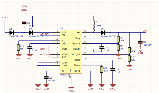
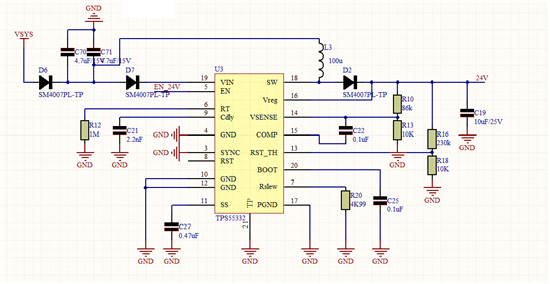
Im unable to get 24 V (300ma) from 12 v and 48V (0.05ma)  from 12 V, the ship overheats and burns (i've checked it thoroughly, no shorts, no bad connections). The 24 v schematic works unloaded at low frequencies (100kHz), loaded does not work at all, at higher frequencies (400KHz) burns out. The 48 v does not work at all.

Below the schematics.

Any help will be really appreciated.

Thanks and regards,


Xavi
 

  • Hi,


    Thanks for your attention, I've finally stabilized the circuit, the problems came because I had a 250 Hz switching inductive load (a Fan). The transients every 4 ms are very strong (11 v minimum and 35 V maximum), the target voltage is 24 V. I've made the error amplifier faster in order to compensate this strong switches, at first time it was 50 to 10 V, but not too much since the intensity peaks were too strong and affected the rest of the board), this is fine for the application since it's a motor. The Gain nor the bandwidth of the error amplifier are in the datasheet, so I had to adjust it trial error, please add them.

    Seems like the problem was that I was trying to work in the CCM mode, i'ts been easier to work in DCM, I still don't know exactly why, if somebody could tell me exactly why i'll be very thankful. The converter's inductance is 2.2 uH@1MHz.

    I'd also like to ask one curious thing I've found, I've used 2 fast diodes, but only one worked, I'm not sure why, the references are the following:

    MURS105T3G : Worked fine

    B340B-13-F: did not work


    Any idea why?


    Regards,


    Xavi


    PD: What burned was the inductance, not the chip, it was underdimensionated, all my fault.

  • hello Xavier,

    so everything is fine now or do you still need help ?

    ciao

    V.

  •  

    Hi Vicenzzo,


    Actually i have no more issues by now, but i'd like to understand why the system didn't work in CCM mode. I tried to run it with 22uH inductance@1MHz, and appears unstable, is it because the load induces heavy transients?Why in DCM is faster?


    Do you have any idea why I had the issues with those diodes?


    May I know the error amplifier gain?


    Thanks and regards,


    Xavi

  • I beg your pardon for the really late reply...

    The diode B340B-13-F burns because has higher Rtj and lower Tjmax compared to the other one; indeed you system 2.2uH @ 1MHz has a pretty huge current ripple that cause the overheat of the diode.

    The difference between CCM and DCM is that the current ripple is higher in DCM and then the system is “faster” to recovery a load transient. Indeed when you apply a load transient the current required by the load is given by the output cap (that is pretty small, by the way); later the energy into the cap is recovered by the choke that transfer its energy to the cap. This energy is proportional to the ripple into the choke and then higher the ripple, faster the system. In particular it is L x I^2 (I=rms), but the total current into the choke has 2 parts, one in DC and one in AC, so


    Ichoke = Idc + Iac = Iout + Iripple (in 1st order approximation)


    Iout is assumed to be constant (and in your case lower than Iripple, in rms I mean) while Iripple is proportional to 1 / L and then the energy is L x 1 / L^2 = 1 / L.

    An inductor of 22uH is probably too high (=too slow) to allow the system work in a stable way because when a load transient is required the system could provide a poor energy compared to the case L = 2.2uH (in which the previous energy is 10 time higher, as explained above).

    The Gain of the Error Amplifier is not supposed to affect the dynamic performance of the system because it is so high that the effects on system response are negligible.

    What you can do is to use a Type 3 compensation network, in which you introduce a derivative branch on the control loop that speed up the system response (but increase noise as well). The difficulty you found out to compensate it is caused by the fact that output cap is a MLCC (with a poor ESR): indeed, in this case, the zero introduce by ESR (fz = 1 / ( 2 x pi x ESR x Cout ) ) is pretty high (because both ESR and Cout are small).

    If you add the DC biasing effect on the MLCC then we can assume you have no cap on the output!!

    This is a common problem in tuning power converters, for this purpose my warm advice would be to turn it into a 100…330uF with a reasonable ESR (15…25mOhm).

    Of course you have to pay attention to the current inrush at the start-up…

    Let me point out that I didn’t apply any formula but just providing you the tools to properly address your issues. Refer to the device datasheet for details…

    I hope I helped a bit…

    ciao

    V.