Other Parts Discussed in Thread: BQ25730, ,
To whom it may concern
We are developing a portable device that integrates TPS25750D and BQ25730, to recharge the internal battery with a USB-C PD mains adaptor.
We have 2 questions regarding the TPS25750D:
Question 1:
At the moment, we have succeeded in getting the TPS25750D to be configured in sink mode and we can control the battery charging without any issue.
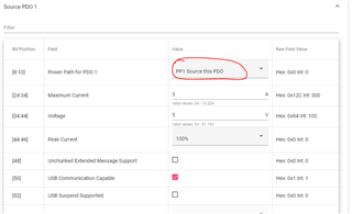
In some use-cases, when the device is running from the battery only, we would like to connect a USB memory-stick (USB type A) to the USB-C port of our device. But we haven’t managed to configure the TPS25750D in source mode to supply the 5V for the USB memory-stick; knowing the PP5V pins are supplied with 5V rail from the battery.
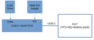
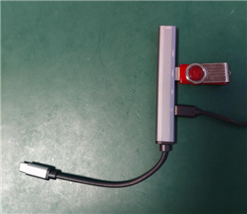
To be noted, when connecting a USB-C PD hub to our device, which the USB-C mains adaptor and the memory-stick are plugged in, we can both power our device and have access to the memory-stick.
So how should we configure the TPS25750D to be in source mode running from the battery? Is there is special command to be sent via the I2Cs? Please find our config.json file attached.
Question 2:
we are planning to use GPIO1 (pin 6) to drive a MOSFET in order to create a ship mode function. In ship mode, most of the internal electronics is disconnected from the battery to limit power consumption; only 3V3 rail from the battery supplies the TPS25750D through VIN_3V3 (pin 38). We managed to control this GPIO as an “ordinary one” by following the TI Technical Reference Manual “slvuan1a.pdf” and by using the commands GPsh and GPsl.
Link to “slvuan1a.pdf”: www.ti.com/.../slvuan1a.pdf
Could you tell us if it is advisable to use this GPIO in such way for the TPS25750D?
Many thanks for your support.
Best regards,
Stéph