This thread has been locked.

If you have a related question, please click the "Ask a related question" button in the top right corner. The newly created question will be automatically linked to this question.

bq24100 STAT1

Other Parts Discussed in Thread: BQ24100, BQ27500

Hi,


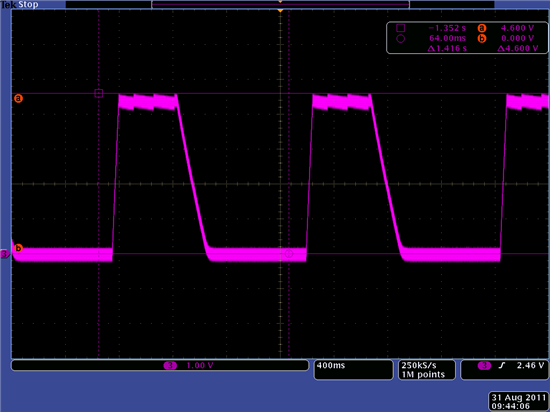
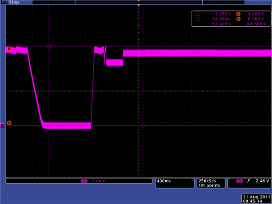
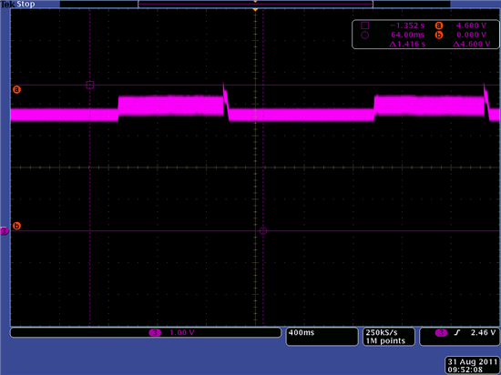
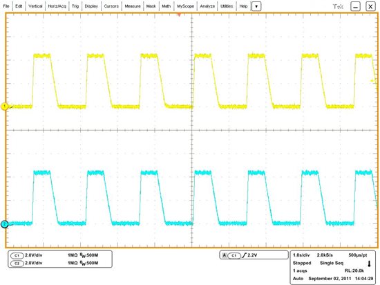
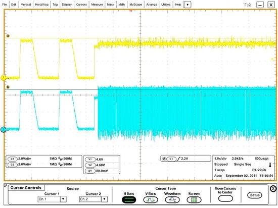
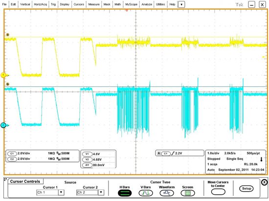
I use the bq24100 to charge a battery pack. As soon as I pull down #CE, STAT1 changes to ON state (STAT2 remains OFF). However, STAT2 immediately changes to OFF again.

What could be the problem? Why does STAT1 does not remain in ON state?


Thank you for your help.

Mike

  • Rony,

    There are several possibilities as to what is happening with your BQ24100 application (from Table 1 on page 17):

    1. The charge cycle could have been suspended: This usually is an issue with the temperature qualificationcircuit (page 14). If the charger senses a temperature condition outside of the normal range of operation it will suspend the charge. It will continue to monitor this until the temperature is within specifications. You might want to check the circuit connected to the TS pin and verify that the circuit is operating properly. You could also apply a voltage directly to the TS pin that is between Vltf and Vhtf (according to your calculations) and this would disable the temperature-sensing feature. I would only do this momentarily to see if the fault was no longer present, as the temperature qualification circuit is a very important safety feature of the BQ24100.
    2. There could be a timer fault: This should not be the case as from your description the STAT1 pin is changing almost immediately
    3. There could be an overvoltage situation: This fault would be initiated is if the BQ24100 sensed that the battery voltage was too high. You could manually check the battery voltageto verify thqat this is not the case.
    4. The other 2 faults are either if the battery is missing or if the BQ24100 goes into sleep mode. These likewise are not very probable.

    I would look at the circuit on the TS pin to verify if everything is operating correctly. It is the most likely fault condition causing the issue that you are seeing.

    Please let me know if you have any additional questions.

    Richard Elmquist

  • Richard,

    Thank youf or your reply.

    I checked the TS pin which has an input voltage of 1.5V. According to the datasheet, this voltage is within the range of Vltf and Vhtf and thus I assume the temperature range is not the problem.

    I also checked point 2, 3 and 4, but I did not find any signal that is not correct.

    Rony

  • Rony,

    Are you using the EVM or is this your own design? If it is your design, please send me a schematic showing the components you are using.

    Are you using the BQ24100 as a stand-alone or system controlled application?

    Are you seeing this issue with multiple chips or just one?

    Have you tried applying a DC voltage on the TS pin without the exterior network present?

    There is a fault condition present according to the status of the STAT pins. We need to determine the actual fault. Please let me the answer to the questions above.

    Richard Elmquist

  • Richard,

    I use my own design: 4201.Schematic.pdf

    I can see the issue with multiple chips.

    What I additionally found out: If I solder the battery with two wires to the charging station, the battery is charged. However, if I connect the battery to the charging station by just pressing the battery to the connection pins of the charging station, the battery is not charged. Is it possible, that the contact resistance causes the problem? Does the bq24100 somehow measure the contanct resistance?

    Thanks,

    Rony

  • By the way, I have another question:

    I use the bq27500 on the battery pack. After programming the device with the DFI file, the remaining capacity as well as the state of charge cannot be read (--> actually can be read but have always the same value). I always have to charge and discharge the battery (about 2-3 times) until this values will be updated. Is there another possibility without doing 2 or 3 cycles counts in order to update the values?

    Rony

  • Rony,

    This is a connectivity issue if the issue happens as you describe. You need to be able to verify that the connector you are using is actually connecting the leads. If they leads are not connected properly with your connector, then the IC will not charge properly. 

    Are the batteries that you are connecting always discharged? If they are not, there could be a large inductive spike that triggers the over-voltage protection. The could also be causing the fault condition you are seeing. This fault should clear itself once the Vibat drops to the threshold voltage.

    I also noticed that you have configured the BQ24100 for a 2A output (Riset1 = 10K and Rsvs = 50mohms), but are not using the recommended inductor size for this application. The datasheet recommends 4.7uH and you are using 10uH. Are you sure the inductor is not going into saturation at that current level?

    Richard Elmquist


  • Richard,

    I tried to charge three batteries. One was fully discharged, one about 40% charged and one fully charged. With the fully charged battery, the charging station did not charge the battery (as expected). With both the fully discharged and 40% charged battery, the charging station starts to charge the battery and stops immediately.

    I changed Riset1 to 11k in order to reduce the maximal current to 1.8A. Further, I replaced the 10uH by a 4.7uH and the 10uF by a 20uF, as recommanded in the datasheet.

    Please have a look at the three graphs.

    - NoBat.png:  Voltage at BAT pin without any battery connected.

    - Cable Connecting.png:  A battery is connected through cables --> the charging station charges the battery.

    - Normal Contacts.png: The battery is connected through the normal contacts (just inserted to the charging station). The charging station always starts and stops charging.

    Regards

    Rony

    NoBat.png: 

    Cable Connecting.png:

    Normal Contacts.png:


  • Rony,

    These shots are from the BAT pin on the IC?

    Can you send me shots from the OUT pin in the same time frame?

    have you measured the actual contact resistance of the connector? This actually could be the issue.  Let me know what you find.

    Richard Elmquist


  • Richard,

    The shots are from the BAT pin. Below, you find the same shots from the BAT pin ( yellow) and the OUT pin (blue).

    The contact resistance is about 1 ohm.

    No Battery:

    Battery with Cable Connection:

     Battery with "Normal Contacts":

    Regards,

    Rony

  • your battery connection resistance is too high.  It should be in the 10s of milliohms.

  • If I connect the batteries with cables to the charging station (battery -> cable -> charging station contact) the resistance is also about 1 ohm and then it works.

    However, I guess that the connect between battery and charging station (without cable) is not constant and sometimes is quite more than 1ohm... Would that be an explanation?

    Is there anything I can do except for changing the contact system of the charging station?

    Regards,

    Rony

  • That could be it or you may have more inductance in the line that has the issue.  More capacitance at the output of the charger would help cancel the inductance.

  • You mean I shall totally remove the inductance (4.7uH) and increase the capacitance (22uF --> 100uF or even more)?

    Regards

    Rony