This thread has been locked.

If you have a related question, please click the "Ask a related question" button in the top right corner. The newly created question will be automatically linked to this question.

TPSI3052-Q1: Schematic Review

Part Number: TPSI3052-Q1
Other Parts Discussed in Thread: TPSI3052

Hi,

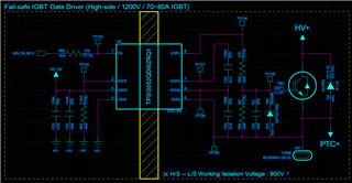
Please review the schematic.

Application : High-side IGBT Control

IGBT : 1200V / 70A / Qtotal = 417nC (typ)

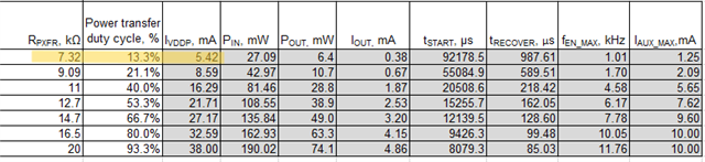
Mode : THREE-WIRE MODE (VDDP = 5V, PXFR = 7.32KΩ, Cin = 1uF+0.1uF, Cdiv1 = 1uF, Cdiv2 = 10uF)

Operating specification: IGBT Turn On/Off (switching specification X)

1. En series resistance = 10 KΩ (R62)

2. IGBT Gate Resistance = 100 Ω (R63)

  • Hi Cho,

    Thank you for your question!

    The capacitors in your schematic are correct. However there are two things I would like to point out concerning the input resistances:

    1. EN - The current that enters the EN pin is a fixed value that is controlled by the selection of the PFXR resistor. From this point of view, the 10k resistor there may not be necessary. Is there another reason for it?
    2. PXFR - Will the IGBT be static switching or switching at a certain frequency? The 7.32k resistor choice here is the lowest possible choice, causing the power transfer to be the least. At this setting, the IGBT could not be switched at higher than 1kHz. If it is static switching, it is no problem.


    Let me know if this answers your questions!

    Sam Skranak

    Product Marketing & Applications | Solid-state relays

  • Hi Sam,

    Thank you for your support.

    1. EN = 10k

    The purpose is to limit the output reference current of the MCU pin because the EN pin is connected to the MCU. (Pin Protection)

    Need to prepare for overcurrent or short circuit by adding a series resistor.

    In EVM test, there was no problem with operation when 5V was applied to the EN pin with 10K resistor.

    If the current consumption of the EN is determined by the PFXR resistor, what is the EN pin current based on 5V / Three-wire Mode / PFXR = 7.32K?

    2. PXFR = 7.32K

    The IGBT using TPSI3052 is not a switching operation.

    When the controller is powered on, turn the IGBT on, and turn it off if the power is off or if there is a problem.

    With the lowest power, IGBT's Turn On can only be maintained.

    Additional questions : Cdiv1 = 1uF, Cdiv2 = 10uF capacity reduction

    Is it okay to reduce the capacitor capacity between VDDH - VDDM, VDDM - VSSS? (Cost Reduction)

    We also confirmed that the IGBT is turned on and the voltage is about 15.2V under the Cdiv1 = 330nF and Cdiv2 = 1uF conditions applied to EVM.

    Please check if there is no problem if we use the same capacitor capacity as EVM under actual usage conditions.

  • Hi Cho,

    Thank you for your patience! Jumping in:

    1. For three-wire mode, the current consumption we care about is in the VDDP pin. Sorry about this, I was thinking in two-wire mode when I answered your question. The EN resistor you have chosen is fine. 

    At 7.32k, VDDP will consume about 5.4 mA.

    2. Our calculator tool recommends that Cdiv2 can be reduced to about 3 uF (between VDDM and VSSS). The 3:1 ratio for Cdiv2 to Cdiv1 must be maintained. This tool is available here if you are curious.

    Let me know if this answers your questions!

    Sam Skranak

    Product Marketing & Applications | Solid-state relays