LM5143A-Q1 does not start when provide power.
Design: single output / 2-phase. Vin: 24V ~ 50V, Vout: 12V
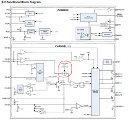
Pin conditions: VCC is 5V, EN1/EN2 are 5V, SS1/SS2 are 5V, HB1/HB2 are 5V.
The device does not drive the FETs at all. Both Outputs are 0V
LM5143A-Q1 does not start when provide power.
Design: single output / 2-phase. Vin: 24V ~ 50V, Vout: 12V
Pin conditions: VCC is 5V, EN1/EN2 are 5V, SS1/SS2 are 5V, HB1/HB2 are 5V.
The device does not drive the FETs at all. Both Outputs are 0V