This thread has been locked.

If you have a related question, please click the "Ask a related question" button in the top right corner. The newly created question will be automatically linked to this question.

TPS92692: Buck Design Reference / Calculations

Part Number: TPS92692
Other Parts Discussed in Thread: TPS92691


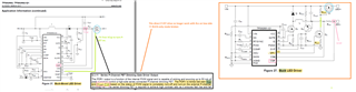
I have inherited a TPS92692 design based on the TPS92691-BUCK topology.

The TPS92692 datasheet does not claim to support the BUCK-only topology where the RCs is on the low-side.
The datasheet also mentions the use of the voltage at CSP, to control the new feature called the "adaptive slope"  control (Vsl is fixed on the previous TPS92691 at 200mV)

This gives me the feeling that the TPS92692 is not the correct part to use forr the BUCK-only topology ...?
There are no WebBench for the TPS92692 that I could find , and no webbench in BUCK Topology for the TPS92691 that could help in verifying the implementation(s)

Can you help me understanding if the TPS92692 can support the BUCK-only topology that the TPS92691 could support.

Thank you.

  • I also see the the "PDRV" will be switching between Vcsp and (Vcsp-7V) which works for a BUCK-BOOST and BOOST topology but would not work in the BUCK topology since in the latter case, the Vcsp comes *after* the digital dimming P-FET...

    In our implementation Vcsp would take the Vgs to (LedVf=9V0 -7V = -16V) but the selected P-FET chosen has an absolute max Vgs of - 12V...

  • Matthieu,

    The TPS92692 is a correct part to replace the TPS92691 in the BUCK configuration.  

    As for the PDRV driver the Vgs is -7V period and not as you mention above.

    Thanks Tuan

  • The TPS92692 datasheet states:

    "The PDRV switches between Vcsp and (Vcsp -7 V)"
    The PDRV internal block is fed Vcsp
    Vcsp in a BUCK-BOOST topology would Vsource of the P-FET (more or less excl drop across Rcs)
    In such a BUCK-BOOSt topology , PDRIVE will therefore create a Vgs= -7V on the P-FET.

    For the BUCK topology, where Vcsp in on the low side and relies on the load being attached, I cannot see it working...Vcsp will be dependent on the LED voltage drop and a further -7V from that Vcsp...


    Additionally, if the TPS92692 was to be suited to the BUCK-only topology, I would be grateful to know how one works out the value for Rslope given that the design calculations use Vcsp in the equation but Vcsp will be dependent on the LED load forward voltage drop which would change with temp/analog dimming control.


  • Matthieu,

    The Qdim will be on the high side like on theTPS92691.  So from VIN it will go to Rcs then to Qdim then to LED anode as the output.  Note that CSP will be tied to VIN and CSN will be tied to the Rcs and Qdim.

    Thanks Tuan

  • Thanks Tuan.

    So I conclude that the <Rcs> location showing on the low side for the TPS92691-BUCK topology, simply needs to be changed to be on the high side when used with the new TPS92692-BUCK topology.

    The design I inherited had maintained the <Rcs> on the low side (as per the older TPS92691-BUCK topology guidelines)

    To work welll with new TP92692-BUCK topology, it appears indeed that one needs to migrate the <Rcs> to be on the high side at which point the controller expected Vcsp would work.

    Thank you for your help.


  • Matthieu,

    Thanks, I'll close this thread.

    Thanks Tuan