This thread has been locked.

If you have a related question, please click the "Ask a related question" button in the top right corner. The newly created question will be automatically linked to this question.

BQ40Z80: BQ40Z80 chip peripheral circuit

Part Number: BQ40Z80

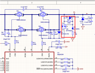
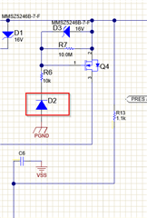
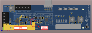
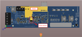
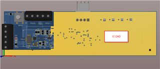
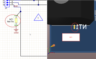
After connecting the anti-reverse circuit shown in the red box in the figure, the test short-circuit protection is not restored, and if the short-circuit protection is still connected to the communication, the communication-related components will be burned out, what is the reason?

  • Hello,

    The reverse circuit protection should not affect the recovery of OCD event. Looking at the differences in your circuit from ours, I can only spot the conventional diode (D6) being above the 10k and not below like in our design. This should not cause the issue you are seeing. 


    Did you test short circuit before adding the reverse circuit protection? 

    and if the short-circuit protection is still connected to the communication, the communication-related components will be burned out

    You mean the components in the SMBus communication lines? Please share the whole schematic if possible. This sounds like the FETs remained open during the short circuit test. 

    Regards,
    Jose Couso

  • Yes, the short circuit was tested before the reverse circuit was added, and the short circuit protection can be restored.

    This is the whole schematic, please help to see if there is any problem.

  • Hello,

    Just to clarify the circuit is a reverse charger protection circuit, not a short circuit protection circuit. 

    There's no big differences between the circuit you added and the one we have in our EVM. 

    I did see a couple of things that might need to be improved.

    1- We recommend to separate the low current paths (IC GND) from high-current path (BAT- ). We often do this by adding either a net-tie or a 0-ohm resistor. 

    See below for EVM example.


    2- It is recommended to add a 10 ohm at each gate of the FETs. This is to avoid ringing and oscillations. See this App Note for best recommendation guidelines.

     Also, please reference to this Thread where common FET failures are discussed during short-circuit tests. Note it is a different device but same principle.


    Finally, you might want to test the short circuit test in our EVM and see if you can replicate the issue. 

    Regards,
    Jose Couso


  • Thank you very much for your answers. I will modify the circuit according to your suggestions.

  • May I ask if the last sentence means to re-layout  according to the EVM schematic,and then test the short circuit.
    You have seen my schematic diagram of the circuit, may I ask what is the difference between my schematic diagram and EVM ?

    And I want to know if the 10 ohm  is applied to all the gates of the FETs or only to the gate of FET for reverse circuits?

  • Hello,

    The 10 ohm is applied at the gate of each charge and discharge FET when placed in parallel. https://www.ti.com/lit/an/slpa020/slpa020.pdf

    I did not see major differences between the schematics. But sometimes it is hard to either find the difference or perhaps it could be a layout issue. Trying the test in our Evaluation Board helps eliminate multiple root causes. 

    Regards,
    Jose Couso

  • RYD-06S-025 V1.0.rar

    These are my schematic diagram and PCB files. Except for the two points mentioned above, could you please check the PCB Layout to see what needs to be improved?
    Thank you very much !

  • Hello,

    I have received your files. I will get back to you.

    Regards,
    Jose Couso

  • Okay, thank you very much. I'm looking forward to your reply.

  • Hello,

    Looking at the layout. Please see below my comments.

    1- It is recommended that the sense resistor is close enough to the IC. Long distance can bring noise and more susceptibility to ESD. 


    2- It is recommended to split the high current path (BAT-) from the low current path (gauge IC GND). See below for an example


    Notice above how the sense resistor lines are isolated. This helps for noise immunity for the coulomb counter.

    Notice how we use a net-tie to split BAT- from IC_GND


    Going to the bottom layer on the sense resistor lines can add ESD and noise susceptibility. 


    The rest looks fine. I see that the input cells RC filter are close enough to the IC. 


    Regards,
    Jose Couso

  • I will make modifications according to your suggestions, and thank you again for your reply.