This thread has been locked.

If you have a related question, please click the "Ask a related question" button in the top right corner. The newly created question will be automatically linked to this question.

BQ25620EVM: How to configure charger IC with microcontroller using i2c communication?

Part Number: BQ25620EVM
Other Parts Discussed in Thread: BQ25620, BQSTUDIO

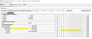
i am using BQ25620 battery charger ic for my application and STM32F0 microcontroller for i2c interface for R/W registers according to my application. please provide any example code to make me understand how to enable ADC_EN register so that it can display VBUS, VBAT etc. values. please help me out ASAP.

  • Hello, 

    Thank you for reaching out via E2E. Unfortunately we do not have sample code available to showcase how to use the ADC feature on the BQ25620 device. Please see my explanation below. A description on the ADC operation can also be found in section 9.3.7 of the BQ25620 datasheet on page 30.  

    To enable the ADC please set 'ADC_EN' bit [REG0x26 bit 7] to 1b. Then to display VBUS and VBAT please perform an I2C read from REG0x2C and REG0x30. Please be aware the ADC control register [REG0x26] is an 8 bit register whereas the ADC output registers are 16 bit registers. 

    Additionally, the BQ25620 GUI in BQStudio software tool can help to visually show the relevant bits for all the various ADC output registers. I have attached a screen capture of the GUI with VBUS output highlighted as reference. 

    Best Regards,

    Garrett