This thread has been locked.

If you have a related question, please click the "Ask a related question" button in the top right corner. The newly created question will be automatically linked to this question.

TPS564252: Hello, i have 1.2V max with my design and it slowly goes lower, what could be the cause

Part Number: TPS564252

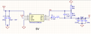
So has mentionned I have done a design for a 5V supply on my board, but i don't have the expected value.

Does anybody know what could be the cause ? The supply also power up very slowly, like more than 5 seconds before reaching 1.2V

Thanks

the Sys rail is beetween 9.6 and 12.6V

  • Hi Noe,

    Thanks for reaching out. My colleague Bruce will help support soon. Thanks!

    BRs

    Lucia

  • Hi Noe,

    Thanks for reaching out! Could you share the information of end equipment, total volume, and also the load? I assume the Vin=9.6-12.6V, and desired Vout is 5V. But the actual Vout is 1.2V with 5seconds slow ramping up right? Correct me if I misunderstood.

    The Vout is not as expected. So, could you provide the waveform of SW, IL, Vout and Vin? And could you use the same condition to test another board to see whether the issue still exists? Also, what is the capacitance of C48 (connected to EN pin)?

    Besides, some suggestions for layout. You can take the below user guide layout as a reference. 

    1. The GND area is too small.
    2. The path from SW pin to inductor should be wide and short to reduce parasitic.
    3. The area of FB should be smaller.

    Feel free to tell me about your more concerns.

    BRs

    Bruce Lu

  • Hello thanks a lot for the response.

    I assume the Vin=9.6-12.6V, and desired Vout is 5V. But the actual Vout is 1.2V with 5seconds slow ramping up right? Correct me if I misunderstood.

    That's correct.

    The Vout is not as expected. So, could you provide the waveform of SW, IL, Vout and Vin?

    I'll send you all the waveform as soon as I can.

    And could you use the same condition to test another board to see whether the issue still exists?

    I have ordered 2 board and it's the same on both board

    Also, what is the capacitance of C48 (connected to EN pin)?

    That is a decoupling capacitance used on antoher IC, it's 10uF, i have tested the 3.3V and it's all in order if it helps you.

    The GND area is too small.

    I have made it a bit bigger, but it's connected on 2 ground plane that are almost the size of the board, and it's a 90 by 75 mm board.
    the board is a 4 layer board.

    The path from SW pin to inductor should be wide and short to reduce parasitic.

    Will change this, thanks,

    The area of FB should be smaller.

    I have reduced the size of the plane to the minimum.

    Thanks, for the help, I'll send you all the waveform, when i find a USB drive that my oscilloscope accepts.

  • Hi Noe,

    Got it! Let's check the waveform when you have it.

    BRs,

    Bruce Lu

  • Hello, my boss want me to do changes on the PCB, so i won't be using this IC anymore.

    Should i delete my post or mark it as resolved

    But thanks for the help anyway.

    Have a good day.

  • Hi Noe,

    Thanks for your feedback. Please mark it as resolved. BTW, which DCDC converter you plan to use next time? Let us know what we can help from our side. Thanks!

    BRs

    Lucia

  • Hello, on this PCB i just won't be using a 5V rail, but next time I'll use one I'll try using this one again, but with a better layout.

    Thanks, have a nice day

  • Thanks for your feedback, Noe!

    Have a nice day.

    BRs

    Lucia