This thread has been locked.

If you have a related question, please click the "Ask a related question" button in the top right corner. The newly created question will be automatically linked to this question.

TPS54313: TPS54313PWPR R-2R model required

Part Number: TPS54313

Good morning,

We are designing a pcb with 2 TPS54313PWPR   units.
And we detected temperature issues, by using Rth provided by datasheet.

Please, could you share the R-2R thermal model, or Delphi thermal model to simulate it in Flowtherm software?
At least, the Rthj to thermal pad.

Thanks you in advance, 

Regards

Daniel

  • Hi Daniel,

    This is a pretty old device and we don't have thermal models for this device.

    Could you describe a bit more about your operating conditions and temperature increase you see?

    Best regards,

    Varun

  • Hi John,

    We have a specific thermal (flight) environmental  with an ambient temperature of 65ºC.
    Our system has to satisfy no Tj exceeds 85ºC.
    Rough calculation by using Rth from datasheet showed temperatured 4ºC above 85ºC.
    We hope that using Delphi or similar model we can reduce it or approach as much as possible in order to validate the design.

    Consider the we have already designed external heatsinks . This issue implies to redesign mechanical aspects or change the component.

    Thank you in advance

    Daniel

  • Hi Daniel,

    Thanks for explaining. Since we don't have a thermal model for this, you could evaluate if these 2 alternate approaches would be a good enough estimate of TJ.

    1. I guess your heat sinks are on the PCB and not connected to the IC package top. This would mean most of the heat generated in the IC would flow through the bottom of the package into the PCB. Since very little heat would flow through the top of the case, the case top temperature should be close to junction temp. You could then measure case top to estimate TJ.
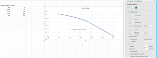
    2. There exists diodes between every pin (n side) and GND pin (p side). Characterizing the diode forward voltage at around 100uA constant current with the IC turned off at different ambient temperatures would give you for example a curve like below. You could add a polynomial trendline of order '2' in Excel to get an equation of the diode forward voltage with temperature. Once you have this equation for TJ, you can run the device at 65C ambient and measure the forward voltage drop. For this test you could try using the diode between FSEL pin and GND. You would also have to take care during diode voltage characterization that the IC has enough time to soak to the ambient temperature so that TJ=TA.


    Best regards,

    Varun

  • Thank you very much