Other Parts Discussed in Thread: TPS7H4001-SP
When using the design calculator for the TPS7H4003-SEP in parallel mode, what is the correct procedure?
For instance, if the total load is 20A and a dual configuration is being used, I'd assume the following:
1. Enter the VIn, Vout, Kind and "10A" as the load current as if the design were for a single phase
2. Enter delta-Iout at 1/2 the expected load step (5A for example given a total 10A load step for the parallel circuit)
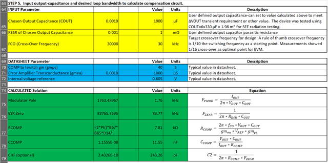
3. Enter the chosen output capacitance suggested based on cells D58, D59 as if it were 1-phase. The actual populated output capacitance will be 2X this value.
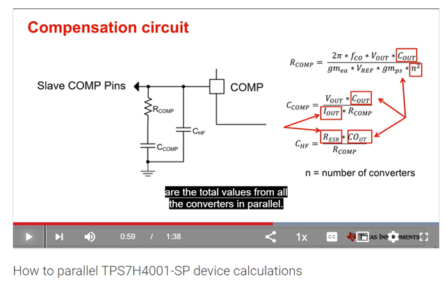
4. The Rcomp calculated value will be 4X (n^2) the value needed for the primary converter compensation, divide the calculated value by 4 and use this for Rcomp (see eqn 37 from the datasheet)
5. Ccomp & Chf calculated values are the correct values to populate in the parallel configuration, no changes? (or should these be doubled based on the output capacitance entered at 1/2 the "real" value?)
Is that correct? Are there any other adjustments required (such as modifying the slope compensation?)
Can we update the spreadsheet to include an "N" factor to accommodate the number of phases?
Thanks,
Steve