This thread has been locked.

If you have a related question, please click the "Ask a related question" button in the top right corner. The newly created question will be automatically linked to this question.

UCC28740: Current Limitation of Pin VS and Operation at 24VDC with UCC28740

Part Number: UCC28740
Other Parts Discussed in Thread: , TL431

Hello,

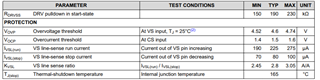
I have encountered some issues while testing the UCC28740. We would like to improve the circuit based on the UCC28740EVM-525 to make it work at 24Vdc. During testing, we found that there was no 5V at the output when using 24Vdc. We gradually increased the voltage, and the test card started operating when the input voltage reached 69Vdc. So, I replaced the resistor R2 next to pin VS and changed to 10kohms. I tested VDD and found that the UCC28740 was in Fault protection. Then, I tested voltages elsewhere, and when I tested VDD again, I found its voltage dropped to 0V instead of oscillating between 7.75V and 21V. I'm not sure about the specific cause of this result; I suspect it might be due to excessive current on pin VS, but I couldn't find information about measuring VS current in the datasheet.

Could someone please provide insight into what might be going wrong and how I can modify the circuit to accommodate a 24Vdc voltage?

Thanks in advance .

  • Hi Eric. I am taking care of this thread and I will be back to you later today.

  • Hi Eric.

    -If you just changed R1 to 10kohm and kept R2 with the same value, the device will go to OVP immediately and will be in protection state. You are changing the voltage divider factor R2/(R1+R2) from 0.2 to 0.75. It will decrease your overvoltage protection almost 4 times.

    -What you need to do is to decrease R2 "N" times, where N is the factor which R1 was reduced. If R1 is 10K now, then N=105/10, and R2*=R2/N.

    Thank you.

  • Hi Manuel.

    Thank you very much for your response; it helped me understand the role of Vcc.

    I hope to use the UCC28740 at 24Vdc. Initially, I thought I needed to change the voltage at the VS , so I modified that resistor. What do I need to change now to use the UCC28740 at 24Vdc?

    Thank you.

  • Hi Eric,

    What you need to do is to change both R1 and R2 (voltage divider resistors at Vs). As I mentioned above, if you changed R1 to 10K, now R2 needs to be reduced with the same factor than R1 was reduced from original value from EVM. Check section 8.2.2.6 from Datasheet where you can find the equations that define both values (see below).

    Thank you.

  • Hi Manuel.

    After replacing a new microelectronic controller, I recalculated according to the two formulas you provided.

    Since our minimum input voltage is 24Vdc, I calculated that RS1 is 27kohm and RS2 is 7kohm. After replacing the resistors based on my calculations, I tested the voltage on Vdd and found it to be in Fault Protection mode.

    What should I do to ensure it operates normally at 24Vdc?

    Thank you.

  • Hi Eric,

    -If the minimum input voltage changes (decreases), the design of the converter changes as well. The EVM is designed for a minimum Vin of 85Vac/120Vdc. The decrement from 120Vdc to 24Vdc is considerable and therefore, the design of the transformer (Lm, Nps), bulk capacitor (Cbulk), Rs1, Rs2 (already discussed) will change as well.

    -I recommend to re-design your schematic using the spreadsheet design calculator tool available in UCC28740 product folder (click on the link below). In this calculator design tool you need to input your input, output and switching specifications (see picture below). What you can do is to use the same parameters specified in the EVM (if it is the case that your design is bases on it) and change the minimum input voltage. These values are reflected in the picture below. Let me know if you have any questions. 

    UCC28740 Design Calculator

    Thank you.

  • Hi Manuel.

    Thank you very much for your response; it has been immensely helpful for us. However, we have encountered a new issue regarding the TL431 that I'm not sure if it might affect you. In the feedback, we have replicated the circuit from the EVM entirely, as shown in the diagram below:

    When I testing the voltage on the pin ref and anode of the TL431, I observed signals like this, and the voltage between pin cathode and pin anode is as follows:

    According to the data on the datasheet, shouldn't Vref be consistently equal to 2.5V? 

  • Hi Eric,

    Yes, Vref should be 2.5V and the anode to cathode should be around 5V. Would you please share your final schematic for a better review?

    Thank you

  • Hi Manuel.

    This is our final schematic:

    The ratio between the primary winding and the secondary winding is 19:7, and the ratio between the primary winding and the auxiliary winding is 19:18.Then, I replaced the resistors on both sides of pin VS and added a 22V diode Zener to protect pin Vdd as shown in the digram. I hope this can be helpful for you.

    Thank you.

  • Hi Eric, I am taking care of this thread and I will be back to you later today. Thank you

  • Hi Eric, I will be back to you tomorrow morning. Thank you

  • Hi Manuel,

    We recalculated and found that we made a mistake in the value of VF in the formula. So, we replaced the resistor values of R2 and R3 on the diagram. The new value for R2 is 82 kohms, and the value for R3 is 36.5 kohms. The circuit successfully operated when the input voltage was 24Vdc. We then attempted to increase the input voltage because we need the circuit to operate at 230Vac. Until 219Vac, the circuit functioned well. However, at 219Vac, we observed that the output voltage dropped from 5V to 0V suddenly. We suspect that the UCC28740 may be damaged, so we tested the voltage on pin Vdd and obtained the following results:

    It seems unusual for an issue to occur on Vdd. However, the fact that R2/(R2+R3) near pin VS is testing at 0.3, similar to the value on the EVM, indicates that there might be a problem elsewhere. Do you have any insights into the specific location of the problem?

    Thank you.

  • Additionally, we did not change two resistors of pin CS during testing. However, later, based on the datasheet formula, we calculated that RCS is 0.214 ohms, and RLC is 429.2 ohms. These values are smaller than the resistances on the EVM. Could you please confirm if these two values are feasible?

    Thank you

  • Hi Eric,

    -If R2=82Kohms and R3=36.5Kohms, the new overvoltage factor R3/(R2+R3)=0.3. This value is greater than the original factor from EVM ( R3/(R2+R3)=0.2). This might lead to an OVP at high Vinac. If the IC is starting correctly at Vdc=24V, R2 design is correct. Calculating your R3 value according to you values and considering OVP=5.20V. R3=49Kohms. Please try with this new value.

    -About, Rcs and Rlc. This values depend on Nps, Nps and Lp. If you changed these values from EVM, I recommend updating those values in your new schematic.

    Thank you.

  • Hi Manuel,

    We replaced the transformer, and our new Nps is 19:7, the turns ratio on the Npa is 19:18, the primary inductance Lp is 82µH, and the transformer efficiency is 70%.

    In addition, I found Vovp is 4.6V on the datasheet. May I ask if Vovp is 4.6V or 5.2V?

    Thank you.

  • Hi Eric, 

    -Vovp=4.6V. This is the overvoltage threshold (from VS pin).

    -Vov=5.2V. This is the overvoltage at Vout (output voltage of your converter).

    Thank you.

  • Hi Manuel,

    And how much resistance should we use for Rlc and Rcs? We calculated Rcs to be 0.214 ohms and Rlc to be 429.2 ohms based on the formula from the datasheet. Are these two resistances too small?

    Thank you,

  • Hi Eric, with your number of turns from transformer and Lp I get Rcs=0.171ohms(considering Iocc =2.5A(overcurrent value when converter goes to CC mode)) and RLC=0.225ohms.

    I recommend updating values from EVM for your new design.

    Thank you