This thread has been locked.

If you have a related question, please click the "Ask a related question" button in the top right corner. The newly created question will be automatically linked to this question.

TPS54283: Shorting On Power Up

Part Number: TPS54283

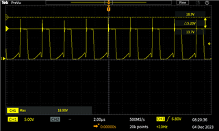
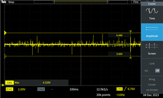
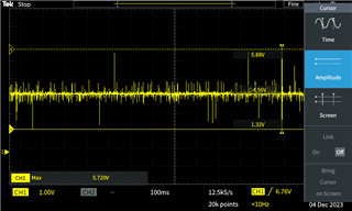
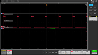
I have designed a non-synchronous switched mode power supply that takes 24V DC in and outputs 5V DC and 3.3V DC using the TPS54283PWP. However when I power the chip using my 24V supply the chip essentially fries itself and looks like it shorts ground to 24V in (it looks like it does this internally within the chip). If I start my input voltage at 1V and slowly crank it up it seems to operate as expected until I reach around the 18V mark and the fries itself again (however I'm not sure if this is just me spinning the knob too crank the supply up quickly at this point). I have triple checked the ratings of all components to make sure they are adhering to the correct ratings and have closely followed the design example in the datasheet for the 24V input. The PCB layout guidelines have been closely followed and adhered too as well as been tested on multiple boards with the same outcome so the problem does not lie within the PCB layout (as I see a lot of answers for this type of stuff refer too). I have attached a schematic of the power supply circuit I am using (verified they are not shorts on the load as the same outcome occurs when I leave the output open circuit). Please let me know if anyone can see anything wrong with the schematic. Note that the 47uF capacitors C11 and C17 are electrolytic polarized caps with a ESR of 400m ohms as suggested by the design examples for stability. Let me know if there are any questions or clarifications necessary, thank you. I will attach the full power supply circuitry but am only really concerned with the TPS54283PWP and surrounding components as the other parts of the power supply have been confirmed working.AudioDemodulator v2.3-Power.pdf

  • Hi Jordan,

    My colleague Bruce will help support this case. Thanks!

    BRs

    Lucia

  • Hi Jordan,

    Thanks for reaching out! Could you share the Vin, SW, IL, Vout waveform of like 12Vin? Since it still works between 1V to 18V.

    Also, it would be better if you can share the layout because I want to see whether it is because the too large ringing of Vsw casued by incorrect layout.

    I will have a more detailed review of your schematic and will soon reply with suggestions, thanks!

    BRs,

    Bruce

  • Hey Bruce thank you for your reply, I am currently not in the office for the next week or so but I will get back to you with those waveforms sometime next week. I will need to redesign the layout... it isn't done per the specs of the datasheet. Please let me know if you find anything wrong with the circuitry so I can definitely blame the problem on the layout.

    Thanks again,

    Jordan

  • Hi Jordan, 

    Got it, thanks! Will wait for the waveforms.

    BRs,

    Bruce

  • Hi Jordan,

    I also calculate the rating of components, for 5Vout, Lmin=35.46uH, Cout=59.9uF, ESRmax=87.5mΩ, R9=1.2kΩ, C20=4.25nF. For 3.3Vout, Lmin=26.7uH, Cout=59.9uF, ESRmax=91mΩ, R12=1.96kΩ, C21=2.81nF. Seems like the rating is ok.

    If possible, could you apply for TPS54283EVM and try with the same components to see whether the issue still exists? Or you can also try use lab DC supply with other non-related IC off-power.

    BRs,

    Bruce

  • Hi Bruce, thank you for the replies. It is not easy for me to try out these components, can you confirm if the components I have chosen should be suitable? From what I can see all the changes you have made there have been from choosing a lower valued inductor instead of my 47uH ones. Is there a downside to choosing a larger inductor value from what I can see there is not maximum value?

  • I have also tested with all other non-related IC stuff disconnected i.e. open circuit load and still not working as well as tired powering the rest of the circuitry with an external power supply and it functions as expected.

  • Hey Bruce I have obtained the waveforms for the Switching pin voltage and the two output voltages (5V and 3.3V) for an input voltage of 13.7V (I can confirm the input voltage waveform is extremely clean) and will attach them at the end of this reply. I couldn't get you a reading of the inductor current as I don't have access to a current probe. The SW waveform has large amounts of overshoot and the two output waveforms are extremely noisy. Do you think that the large overshooting on SW is killing my IC for the input voltage of 24V? Also would this overshoot be the cause for the high amounts of noise on the two output voltages? Finally can these problems all be explained by the PCB layout? I am unable to share my layout with you due to proprietary issues however it definitely did not follow the layout guidelines from the datasheet. Thanks for all your help.  

  • Hi Jordan,

    I think the components you have chosen are all right, aligned with the values I calculated. And the 47uH inductors you have chosen should be ok. The SW waveform seems off-normal, too large ringing before the high-side was ON, it’s very likely to be the reason to cause your IC breakdown and also the output noise. I have also reviewed your schematic, no serious problems. So, I think it would be good to take a review of the layout and follow the layout guidelines in the datasheet. Could be the too large parasitic, you can try with different Iout and see whether the overshoot changes. We also have the layout in the datasheet and EVM user guide, you can take those as a reference.

    However, I’m going to test my TPS54283EVM with the same components and will reply to you when I got the waveforms.

    BRs,

    Bruce

  • Hey Bruce thank you very much for all the help I will begin doing the redesign of the layout now closely adhering to the guidelines in the datasheet. I will wait for your results before ordering new boards to ensure that I can blame the malfunctioning on the layout. Again thank you very much for all the help I really appreciate it.

  • Hi Jordan,

    Your welcome. Will share you once we have results with TPS54283EVM board. Thanks!

    BRs

    Lucia

  • Hey guys any update on the testing? 

  • Hi Jordan,

    Bruce is doing the bench test and he will share you the EVM results tomorrow.

    Thanks for your understanding!

    BRs

    Lucia

  • Hi Jordan, sorry I got delay because it took me some time to find a proper diode, since the diode in original EVM board didn't support >20V voltage. By the way, could you check the rated voltage of the input capacitor & diode you used? or you can share the part number directly.

  • Thank you Lucia

  • Hi Bruce no worries. The 10uF input capacitors (part number GRM21BR61H106KE43L) are rated for 50V DC and the diode (part number

    SL44-E3/57T) has a reverse voltage of 40V. Let me know if you need any more information and thanks again.
  • Hi Jordan,

    Just finished my test of TPS54283 on EVM, with 47uH inductors and 47uF output capacitor. It works normally at 24Vin, 3.3/5Vout and 1A. Below is the waveform. Kindly let me know the actual load current so that we can check the behavior according to your application.


  • The 13.7Vin 3.3/5Vout 1A waveform, of Vsw, Vout.


    BRs,

    Bruce

  • Hi Jordan,

    Understand the condition that you are unable to share your layout due to proprietary issues. Not sure if you could share us by email and send to lucia-gao@ti.com. If not, please refer to datasheet layout guide or I can send you EVM layout if you need for your reference when you update your second version layout.

    For the damage issue, please check other potential reasons:

    <1> Vin Cap too far away causing SW spike too high or too negative to cause LSF or HSF damage

    <2> Input voltage surge/ESD

    <3> Input power supply bad performance

    <4> Production test induced over voltage event

    <5> Boot cap too small or too far away from IC pins

    <6> Inductor saturation current too small

    <7> Peripheral components missing/quality issue (Vin Cap, Boot Cap, FB resistor, etc.) causing internal logic mal-function

    <8> IC pin to pin short causing EOS

    <9> Soldering quality issue causes components open/short or IC pin open or pin to pin short

    Thanks!

    BRs

    Lucia

  • Hi Jordan,

    When you are designing your second version board, we do want to mention that we have new released device TPS62933 which is 3.8-V to 30-V, 3-A, 200-kHz to 2.2-MHz, low-IQ synchronous buck converter in SOT-583 (1.6mm x 2.1mm) with great performance:

    • Adjustable high SW Frequency(200-kHz to 2.2-MHz) with internal compensation for low solution cost and size
    • Lowest Iq(12uA) 30V 2A/3A buck converter in the market for high light-load efficiency
    • Optimized pin-out for easy PCB layout and EMI performance
    • All serious family for PG/SS, FCCM/ECO/OOA(out of audio) options

    Let us know if you are interested about this new released device in your project or maybe in the future.

    Thanks!

    BRs

    Lucia

  • Hi Bruce thanks a lot for testing that stuff out for me just to confirm are you using the same components as I used in the pdf of the schematic I attached in the original question? Also your Vsw is definitely a lot cleaner than mine however I'm still seeing quite a significant overshoot is this expected? (I honestly thought I was frying the chips due to poor pcb layout and large overshoot) however it looks to me as though the overshoot wasn't actually the thing frying the chips? My typical load current will be very low and in the range of only 200mA  - 300mA. Thank you. 

  • Hey Lucia I am still in the process of redesigning the pcb layout, thank you for those tips I will keep them in mind when designing it. I will send you the pcb layout via your email when completed for review, thank you very much! 

  • Actually I have just found the old board's layout I will send you the pcb layout of the power supply now to your email, thank you for that. 

  • Hi Jordan,

    I got your email and will give you response by email. We will close this thread first. Thanks!

    BRs

    Lucia

  • Hi Jordan,

    We have not seen an update from you for one month, so I assume the questions are answered and the issue is solved.

    If you don't have any further questions, can you please close the thread by clicking on resolved. Clicking the Resolved Button also helps us to maintain this forum. Thanks!

    BRs

    Lucia