This thread has been locked.

If you have a related question, please click the "Ask a related question" button in the top right corner. The newly created question will be automatically linked to this question.

LM3478: Heating issue

Part Number: LM3478

Hi,

Good day,

I am using LM3478 in buck boost config where my input range will be 10-15V and my output will be 12V and 2.5Amps max. In my current implementation the mosfet is heating  and my whole board is heating for  even for 1amp of load, is this phenomenon expected.

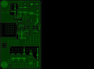
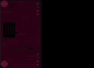
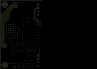
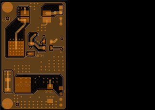
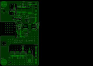
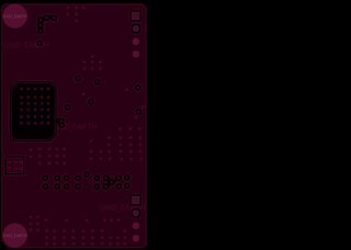
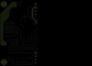
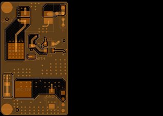
i have attached the schematics and the images of my layout for your reference,

    LM3478 (1).pdf


Thanks in advance,

Regards,

Saiprakash.C.J

  • Hi Saiprakash,

    thank you for using the E2E forum.

    In general some heating needs to be expected as there is always some losses in a SMPS.

    Can you check your efficiency - this would give some more details.

    How much is the heating?

    Is your output voltage stable?

    Also check if the input voltage is stable - so your supply can properly provide the required current.

    C26 should be on the other side of R14.

    Best regards,

     Stefan

  • Hi stefan,

    thanks for your reply,

    Input voltage - 15v constant and same with 10.5V

    output voltage - 11.9 constant in both the inputs.

    my board is heating up to 60 and my heat sink is heating up to 70 Celsius.

    how can i check my efficiency? This is my first time in designing a power supply. 

    Is the layout oky?

    Regards,

    Saiprakash

  • Hi Seiprakash,

    efficiency = (I_OUT * V_OUT) / (I_IN * V_IN)

    To check the layout it would help to also have an image with the reference designators to identify the location of the components.

    There is a quite large hole in the ground area which might influence the current return path in a negative way.

    Best regards,

     Stefan

  • Hi Stefan,

    this following are the efficiency of different modes,

    buck mode

    Vin was 10.5 and Vout was 11.9 with 92%

    Boost mode

    Vian was 15.04 and Vout was 11.9 with 87%

    is this efficacy fine for a SEPIC.

    Please find the Layout images attached,


    Regards,

    Saiprakash.C.J

  • Hi Saiprakash,

    this efficiency is in a expected range (as you can also see this in this reference design: TIDT346.PDF)

    I think the layout looks OK.

    Best regards,

     Stefan

  • Hi stefan,

    We can close the case.

    Thanks for the help.

    Regards,

    Saiprakash

  • Hi Stefan,

    Good day,

    just wanted to know something, I am putting 2 amps of load now. and the board is heating up to 80 and the junction is reaching up to 103 degree. Is this expected.

    Regards,

    Saipraksh.C.J

  • Hello Saiprakash,

    With an output power of 24W and an efficiency of 87%, the system (mainly the FET) will burn more than 3W.
    In that case I would expect a temperature rise of about 80 degrees or even more.

    Best regards,
    Harry

  • Hi Harry,

    good day,

    thanks for your reply,

    So the heat is expected and i have to figure out a way to dissipate the heat right?

    Regards,

    Saiprakash.C.J

  • And is there a possibility to reduce this heat by choosing an even more better mosfet if yes can you suggest me a better one?

  • Hello Saiprakash,

    There are mainly two types of losses in the FET: Switching losses and Conducting losses.

    To reduce the switching losses, you can reduce the switching frequency, if possible. 
    This may result in a higher ripple of the output voltage.
    So you will need to find a good compromise there.

    To reduce the conducting losses, please select a FET with a very low RDSon.
    Please understand that I cannot give a recommendation of a particular device or supplier.

     Best regards,
    Harry

  • Hi

    I also have another concern where the Inductor is heating up a lot than the mosfet. inductor is the one who is heating up  the board than the mosfet.inductor part(DRQ-127-6R8-R)

    Regards,

    Saiprakash

  • Hi Saiprakash,

    Thanks for the update.
    If your inductor is heating up a lot, this may be related to a very large current ripple, resulting in larger inductor losses.
    You can calculate your current ripple using our power stage designer tool. Please choose the according topology, enter all parameters and double click on the inductor within the schematic to see the current waveforms. The tool also recommends you a suitable inductance for you application. If your chosen inductance is much lower than the recommendation, please consider replacing this part.
    https://www.ti.com/tool/POWERSTAGE-DESIGNER

    Best regards,
    Niklas