This thread has been locked.

If you have a related question, please click the "Ask a related question" button in the top right corner. The newly created question will be automatically linked to this question.

UCC256404: VCC not Stable at No Load Condition

Part Number: UCC256404
Other Parts Discussed in Thread: UCC28180

Hi Team,

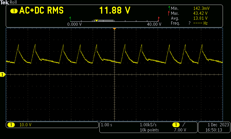
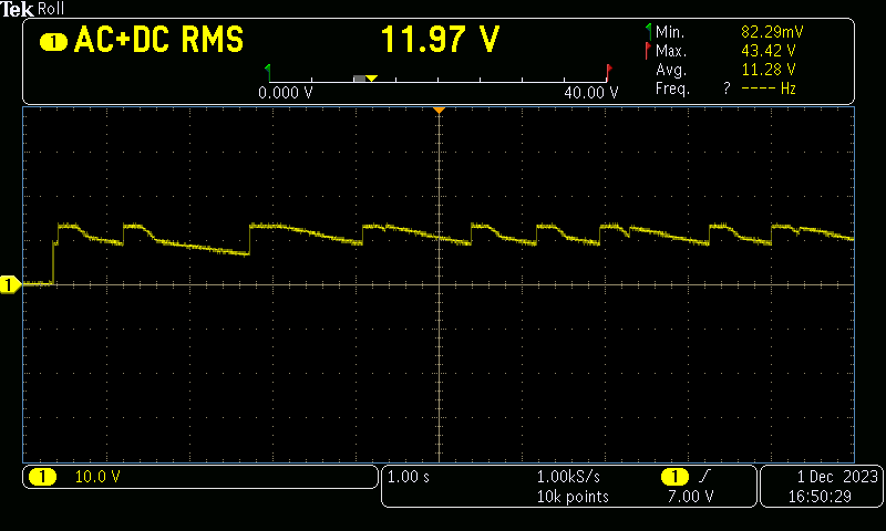
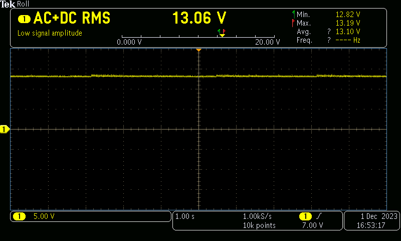
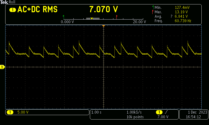
We have designed the 14.6V 30A using UCC256404 without Aux power Supply. The chip VCC will be powered from the Primary bias winding with post regulator of 15V. The Secondary side also will be powered from the Aux winding to the CC CV Controller TL103 for the feedback. (Secondary side design is based on TI PMP40766 reference design). RVCC will be given for the PFC UCC28180 VCC. We are facing issue at the output is in no load condition. During no load condition the VCC will be fluctuating between 12 ~ 19VDC. Once we loaded the output of 0.1A means the output & Chip VCC will be stable. There is no issues up to 0.1A ~ 30A. So we currently we added preload resistor of 100E at the output. How to solve the issues at no load condition.

LL/SS R: Upper: 270K, Down: 120K, & C : 220nF

Regards,

Nishanth M

  • Hi, 

    When VCC oscillates, is 14.6V stable? Do you have 14.6 output waveform?  I assume there are 4 winding on the transformer, Primary aux winding; Primary main; secondary main, and secondary aux? Is it correct?

    Thanks,

    Sean

  • Hi,

    1. When VCC oscillates, is 14.6V stable? — No

    2. Do you have 14.6 output waveform? — No, but I can share it asap. Oscillates from 13 ~ 14V.

    3. I assume there are 4 winding on the transformer, Primary aux winding; Primary main; secondary main, and secondary aux? Is it correct?  — Yes 

    Regards,

    Nishanth M

  • Hi, 

    Please check out the waveforms at no load condition at secondary side and Let me give solution to solve the problem...

    1. UCC256404 VCC:

    2. UCC256404 RVCC

    3. Secondary Main 13V (Currently we tuned it for the 13V instead of 14.6V)

    4. Secondary Aux Supply after Post Regulator: 12V (Power for TL103)

    1. Check out the below values when we load the 0.1A at secondary 13V.

    UCC256404 VCC:   16.7 ~ 17.55V

    UCC256404 RVCC: 13.03V

    Secondary Main: 12.99V

    Secondary Aux: 12.5V (after post Regulator)

    Secondary Aux: 18.5 ~ 19.5V (Before post Regulator)

    2. Check out the below values when we load the 2.1A at secondary 13V.

    UCC256404 VCC:   18.79V

    UCC256404 RVCC: 13.03V

    Secondary Main: 13.10V

    Secondary Aux: 12.5V (after post Regulator)

    Secondary Aux: 21.2V (Before post Regulator)

    Kind Regards,

    Nishanth M

  • Hi Nishanth,

    The VCC is dropping below the VCC restart threshold which is caused due to infrequent switching during burst mode.

    You can try following methods:

    • Increase the VCC capacitance.
    • Reduce the BMTL threshold by either adjusting the LL/SS resistor divider or by reducing the capacitance between VCR and ground.

    Regards

    Manikanta P

  • Hi Manikanta,

    We tried but the problem remains same. Let me help to solve the issuse.

    • Increase the VCC capacitance. -- Added 470uF/35V Electrolytic at VCC.
    • Reduce the BMTL threshold by either adjusting the LL/SS resistor divider or by reducing the capacitance between VCR and ground. -- Reduced capacitance 6800pf to 4700pf at VCR Pin to ground.

    LL/SS R: Upper: 270K, Down: 120K, & C: 220nF

    VCR: Upper: 68pF & Down: 4.7nF

    BW: Upper: 36K & Down: 5.6K Cap: 3.9pF

    VCC Cap: Before Post Regulator Bias Winding: 470uF & After Post Regulator: 220uF & At VCC Pin: 470uF + 100uF + 2.2uF + 0.1uF

    Regards,

    Nishanth M

  • Hi Nishanth,

    Could you let me know whats the burst packets frequency (packet to packet duration) during no load.

    Regards

    Manikanta P

  • Hi Manikanta,

    Please check out the below Gate waveforms of the LO at the No load Condition. Let me help to solve the issues...

    Regards,

    Nishanth M

  • Hi Nishanth,

    Could you try removing upper LL/SS resistance. This would make BMTL as 0.2. currently it was set at 0.361V.

    Also, could you share your design calculator and schematic. I would like to see the resonant tank parameters. 

    Regards

    Manikanta P