This thread has been locked.

If you have a related question, please click the "Ask a related question" button in the top right corner. The newly created question will be automatically linked to this question.

UCC28070: single-phase totem pole PFC

Part Number: UCC28070

Dears,

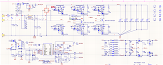
  Customer use UCC28070 to design single-phase totem pole PFC, half-wave rectification distortion, waveform as below. The diode is disconnected from the GND of the IC, grounded separately, or the inductor is disconnected, and the waveform returns to normal. 

Need help to confirm two issue,

1. Whether UCC28070 can used for single-phase totem pole PFC.

2. Whether the circuit can still be modified.

  • Hello User 5883945, 

    Your customer does not identify what signal is displayed on the 'scope.  Part of it resembles the VINAC signal, so I will assume it is the voltage across R73 (on the VINAC input). 
    My comments are all based on this assumption.  Please correct me if I am wrong.

    The signal appears to be clamped to ~2V.  The schematic shows a diode D76 to a voltage 3.3V.  I assume then that 3.3V is not regulating and its voltage is more like ~1.3V.
    Please check the 3.3V output.  

    Why are VINAC and VSENSE clamped to 3.3V (+ Vd)?  This is dangerous, since if 3.3V is not regulating, VSENSE cannot detect VBUS if it goes over-voltage and will not shut down PWM.  
    ==>  I strongly recommend to remove D31 and D76.  

    VINAC and VSENSE also go to AI_VAC and AI_VBUS through 100R resistors.  
    What kind of loading impedance do AI_VAC and AI_VBUS represent?  They should not load the VINAC and VSENSE signals at all (very high impedance) or malfunction can occur. 

    The signal at RSYNTH is connected to Vref through R84.  This is a mistake.  I think the intention is to sense Vref (similar to AI_VAC and AI_VBUS) and maybe the signal on R84 was intended to be "AI_Vref", like this:

    I think the UCC28070 can be used for totem-pole bridgeless PFC, but some circuit connections do not look right. 
    I am not an expert on TP-PFC, but I think the upper MOSFETs Q3 and Q4 also need current-sensing in their drain paths. Without this, the negative half-cycles will not have any current control.  Interconnecting the current sensing should be straight forward, but I don't think T1 and T2 need to have full-wave rectification.   
    You'll need a T3 and T4 for sensing at Q3 and Q4.  Their rectified outputs can connect across R91 and R94.

    The gate-drive interfaces between the UCC28070 and Q3, Q4, Q6, and Q7 are not shown.  I don't know how complicated the drives must be for TP-PFC using UCC28070. 
    I'm sure it can be done with enough circuitry, but I don't know the details.  I assume that Q2 and Q5 are disconnected for now, but are possible synchronous rectifiers to replace the diode bridge in the future.  

    Regards,
    Ulrich