Hi,
In a booster circuit using lm3478 , The output oscillates when the load changes.
Vin is +24V ,Vout is +80V and 0.3A .
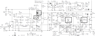
The circuit diagram and oscilloscope image are shown.
Please give me advice to solve this problem.

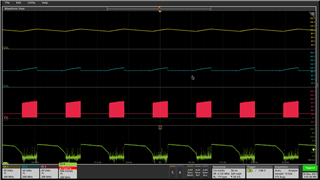
yellow : Vout , green : FB

yellow : FB , blue : COMP
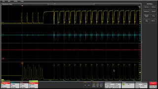
yellow : Q11 gate , green : Q11 drain