This thread has been locked.

If you have a related question, please click the "Ask a related question" button in the top right corner. The newly created question will be automatically linked to this question.

UC2844: Operation errors

Guru 11480 points
Part Number: UC2844


Hello,

My customer is testing the UC2844N on a board they designed with the conditions below.

  - specification : 220VAC±20% Input, 28V/3A output, Effi 85%

  - Switching frequency : 70kHz

  - Topology : Flyback

  - Control IC : UC2844N

  - Transformer :`


Error symptom 1 : Burst mode operation when load is applied - actual output falls in the burst section and rises in the pause section


             Ch1. Vgs, Ch2. Vo, Ch3. Isense, Ch4. Vds

Error symptom 2 : Isense noise occurs when FET switching ON/OFF - Isense noise -> Output noise


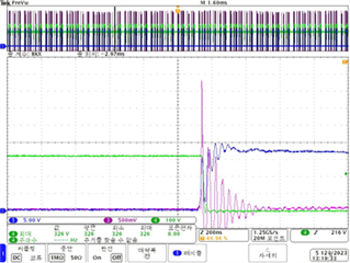
          Ch1. Vgs,  Ch3. Isense, Ch4. Vds

Q1. Please advise on the causes and solutions for the above error symptoms.

Q2. Could you please review the circuit privately to see if there are any problems?

Thank you.

JH

  • JH,

    1. Gate drive shows high frequency ringing - try increasing grate resistor and also check VCC pin to make sure it is pure DC without any glitches, dips or ringing
    2. VGS is ramping downward - another indication that VCC may not be stable. check the VCC capacitor which should be several/ten uF in parallel with 0.1uF high-frequency bypass ceramic cap. Make sure the 0.1uF cap is p[laced directly at the VCC/GND pins of the PWM.
    3. CS signal is discharging very slowly - make sure it is not over filtered by some large RC
    4. CS signal has huge leading edge spike - could be related to PCB layout, transformer leakage inductance, reverse recovery of secondary-side diode?
    5. UC2844 does not have "burst mode" but what you are likely seeing is the COMP voltage falls below the minimum threshold, pulses will stop until the COMP voltage returns. This is uncontrolled and somewhat random. Pulses are randomly missing as opposed to periodically skipping. It a[appears the control is not stable. Stabilize the current loop first (make the current sense signal as clean as can be), then stabilize the voltage loop.
    6. Check out topic 3: Design Review: A Step-by-Step Approach to AC Line Powered Converters.
    7. Check out TI Reference Design Library for similar design examples. Here is a filtered list close to your requirements.

    Regards,

    Steve