This thread has been locked.

If you have a related question, please click the "Ask a related question" button in the top right corner. The newly created question will be automatically linked to this question.

TPS61021A: High shutdown current on initial power-up

Part Number: TPS61021A
Other Parts Discussed in Thread: TPS62243

I have a design which uses the TPS61021A to generate 3.6V from a AAA alkaline battery. The enable pin is pulled to ground through a 100k resistor and the design holds the regulator in shutdown mode until a button is pressed. I have found that upon initial application of power on a cold start I see an input current of about 40 uA at 1.5V and the output voltage floats around 0.25 V. If I enable the regulator then disable it the shutdown current drops to < 1 uA at 1.5V and the output voltage goes to 0.0 V. If I remove power and re-apply it the shutdown current remains at < 1 uA at 1.5V and the output voltage remains at 0.0 V. Per the datasheet I would expect to see the shutdown current at < 1 uA even at initial application of power.

I have probed the enable line with an oscilloscope and it remains below the EN high threshold during power-up. What is causing the high shutdown current on initial power-up? Does this device not enter shutdown mode after power application until the EN line is cycled high then low? The 3.6V rail generated by the TPS61021A powers a TPS62231 generating 1.8V and this regulator has its EN line tied to VIN. Could this 1.8V regulator be causing issues with the upstream regulator?

  • Hi Robert,

    Can I see the waveform of the high current shutdown.

    I think it'll be good if we can see the waveform of inductor current, EN pin voltage and voltage on SW pin.

    Best Regards,

    Travis

  • Hi Travis,

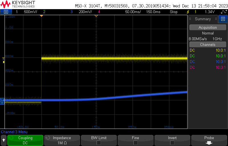
    I have done my best to capture useful waveforms. I found that the high shutdown current always occurs when VIN is hot-plugged, so each capture was taken when VIN is hot-plugged to 1.500 VDC. The oscilloscope channel mapping is below.

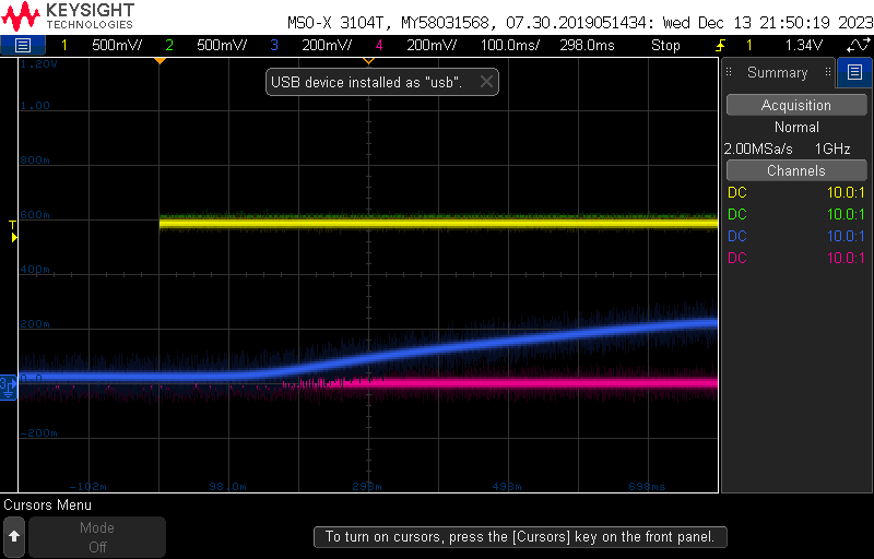
    CH1 (yellow) is VIN.

    CH2 (green) is SW.

    CH3 (blue) is VOUT.

    CH4 (pink) is EN.

    This waveform shows all four signals together. You can see VOUT slowly rise to 0.22 V after power is applied. All four oscilloscope probes shared a ground path which is rather long so all the signals are quite noisy. The next plots used a short dedicated ground on the signal of interest to remove the noise. Regardless, I do not see the EN line go above the logic high threshold of 0.84 V.

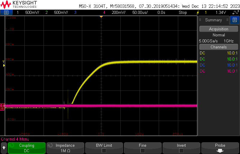
    This waveform shows the EN line on power-up.

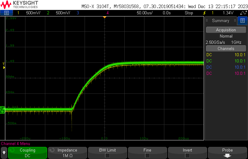
    This waveform shows the SW line on power-up.

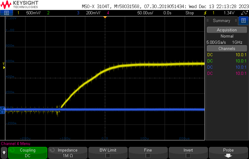
    This waveform shows the VOUT net on power-up on a short timescale.

    This waveform shows the VOUT net on a longer timescale, showing it begin to rise to 0.22 V.

    I am unable to capture the inductor current directly due to the low magnitude of the current draw but in each of these plots the DC current drawn from the power supply was 40-44 uA.

  • Hi Robert,

    Thanks for your waveform. I cannot repeat your phenomenon on bench, so I would like to see your schematic and layout.

    Best Regards,

    Travis

  • Hi Travis,

    I have identified the root cause of this issue. There was a microcontroller pin attached to the power input through a 10k resistor and I believe the I/O pad was latching up on hot-plug. This pad then leaked current into the 1.8V rail which powers the mcu, and the 1.8V regulator TPS62243 then backfed the 3.6V rail and the 3.6V regulator TPS61021A was partially powering on by sinking this current through its VOUT pin.

    Thank you for looking into this issue with me. The 3.6V regulator TPS61021 is functioning properly and does not have an issue.