This thread has been locked.

If you have a related question, please click the "Ask a related question" button in the top right corner. The newly created question will be automatically linked to this question.

TPS25751: TPS25751 development problems

Part Number: TPS25751
Other Parts Discussed in Thread: TPS25750, , BQ25731

Dear TI support,

we are currently trying to continue the development of our smart power bank with replaceable 4s battery after switching from TPS25750 to TPS25751.

We are facing some problems, could you please point us in right direction?

1) We noticed that patch download doesn't work on 400000kHz I2C timing, we had to lower the CLK frequency to 200000kHz to make it work. On higher CLK (400000kHz) we never passed step 11 (Read DATA1 = 0 Successfully completed - we read always 64) in patch download flowchart. Is this known issue?

2) We configure the TPS25751 in the way attached TPS25751_config.json shows. The device operate correctly in Sink mode, connected to Source power supply it establishes PD contract and powers up our battery charging block (we use BQ25731 charging IC).

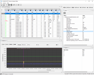
3) When we disconnect from external power source (Source) and connect ST development Sink device, it establish PD contract at 5V / 3000mA and so far works fine. The problem is, when we try to switch to higher voltage contract (9V / 3000mA), we enable OTG mode on BQ25731 to output 9V, then we select on ST development board to establish contract wit PDO2 (9V / 3000mA) but this never passes and ends up always with HARD RESET (see attached picture from PD analyzer).

4) Which GPIO signal can be used for BQ25731 OTG mode enable? Is it enablesource_port1 (73)? This signal goes high right after 5V / 3000mA PD contract is established and stays high

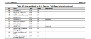
5) We need to be checking the state of TPS25751 in order to display correct information (sink info - battery charging and battery state or source info - output current etc) on embedded OLED screen, so we tried to observe the state of TPS25751_REG_RX_TYPEC_STATE register and especially its 31-24 bit field - TypeC Port State. This bits seems to show correct 0x60 - Attached.SRC or 0x61 - Attached.SNK state, but sometimes, occasionally it show 0x01 state, which is not described anywhere and this is causing us troubles in how to detect TPS25751 state from host MCU. Any thoughts, please?

thank you

  • TPS25751_config.json.txt
    {
      "questionnaire": {
        "device": "TPS25751",
        "answers": [
          null,
          0,
          4,
          4,
          0,
          0,
          3,
          0,
          1,
          1,
          1,
          0,
          0,
          0,
          16.8,
          4,
          0.2,
          0.32
        ],
        "vendorId": "0000",
        "productId": "0000",
        "version": "1.0.0.2"
      },
      "configuration": {
        "data": {
          "selected_ace": [
            {
              "register": 22,
              "data": [
                10,
                56,
                48,
                205,
                0,
                0,
                0,
                15,
                0,
                0,
                3
              ]
            },
            {
              "register": 41,
              "data": [
                210,
                80,
                201,
                0
              ]
            },
            {
              "register": 50,
              "data": [
                5,
                84,
                41,
                44,
                145,
                1,
                0,
                44,
                209,
                2,
                0,
                44,
                193,
                3,
                0,
                44,
                177,
                4,
                0,
                244,
                65,
                6,
                0,
                0,
                0,
                0,
                0,
                0,
                0,
                0,
                0,
                0,
                0,
                0,
                0,
                0,
                0,
                0,
                0,
                0,
                0,
                0,
                0,
                0,
                0,
                0,
                0,
                0,
                0,
                0,
                0,
                0,
                0,
                0,
                0,
                0,
                0,
                0,
                0,
                0,
                0,
                0,
                0
              ]
            },
            {
              "register": 51,
              "data": [
                5,
                44,
                145,
                1,
                16,
                44,
                209,
                2,
                0,
                44,
                193,
                3,
                0,
                44,
                177,
                4,
                0,
                69,
                65,
                6,
                0,
                0,
                0,
                0,
                0,
                0,
                0,
                0,
                0,
                0,
                0,
                0,
                0,
                0,
                0,
                0,
                0,
                0,
                0,
                0,
                0,
                0,
                0,
                0,
                0,
                0,
                0,
                0,
                0,
                0,
                0,
                0,
                0
              ]
            },
            {
              "register": 55,
              "data": [
                59,
                64,
                31,
                65,
                144,
                145,
                1,
                0,
                6,
                0,
                0,
                0,
                0,
                0,
                0,
                0,
                0,
                0,
                0,
                0,
                0,
                0,
                0,
                0
              ]
            },
            {
              "register": 60,
              "data": [
                10,
                0,
                1,
                0,
                1,
                54,
                0
              ]
            },
            {
              "register": 92,
              "data": [
                255,
                12,
                0,
                0,
                0,
                0,
                0,
                0,
                0,
                16,
                0,
                0,
                15,
                4,
                0,
                0,
                48,
                4,
                0,
                0,
                0,
                0,
                0,
                0,
                15,
                12,
                0,
                0,
                0,
                0,
                0,
                0,
                10,
                0,
                0,
                0,
                73,
                97,
                99,
                97,
                0,
                0,
                21,
                3,
                0,
                0,
                0,
                1,
                0
              ]
            },
            {
              "register": 112,
              "data": [
                0
              ]
            },
            {
              "register": 152,
              "data": [
                26,
                0,
                0,
                0,
                0,
                0,
                170,
                0
              ]
            }
          ]
        }
      }
    }

  • 1.  There code that does the patch download did not change between the 2 devices, so this is not an expected change.  It is possible that the new firmware would require a slightly larger delay between the commands and the patch transfer.  We have seen this resolve issues in the past, but changing the transfer speed should not cause a change as long as you do not see NAK errors in the transfer.

    2.  Understood

    3.  Do you see the appropriate I2C traffic to update the charger when transition to 9V?

    4.  You can use the enablesource_port1 event for OTG_EN on any GPIO

    5.  This I will need to look into what is happening here.  This is a preview device and my need some update.  Here is an explanation of what a preview device is at TI:  https://www.ti.com/support-quality/quality-policies-procedures/product-life-cycle.html

    Regards,

    Chuck

  • 1. OK, adding 1ms delay before PBMs CMD1 write, before CMD1 read and before DATA1 read did solve the problem and we can be working back at 400000kHz, thank you for the tip. Interesting that delay just before DATA1 read did not help...

    3. We set up statically 9V output from BQ25731 OTG and then it does not work when we intend to establish PD contract at 9V. This was sometimes working with TPS25750 and now it is not working at all. Could the problem be caused, that 9V OTG is turned on all the time even during 5V 3A contract?
    4. Here I want to ask what GPIO signal/feature/internal register is intended to be used for charger OTG setup and output voltage enable before PS ready message. I was thinking gpio enablesource_port1 is intended for this purpose, but it stays high all the time after 5V 3A contract is established. When I try to change PD contract to 9V 3A it will never go low and high again to signal new charger settings should be applied.
    5. Same behavior was with TPS25750. I'm looking for some reliable way how to know TPS25751 is connected to Source or Sink and with established PD contract.
    thank you for your help
  • Jan,

    Do you have the capture of the I2C bus between the TPS26751 and the BQ25731?  I need to see the signals so that I can help address what is going wrong.

    Regards,

    Chuck

  • We don't use direct I2C interface between the TPS25751 and the BQ25731, we controll both from host microcontroller. That is why I asked point 4.

  • Jan,

    The enable source event will transition high anytime the PD controller is a source, so it should work for that purpose.

    The reason that I want to see the I2C signals is so that I can see if our part is sending the correct I2C transactions at the right time.

    Regards,

    Chuck

  • As we don't use direct I2C interface between the TPS25751 and the BQ25731, do you want us to send you I2C signals between MCU and TPS25751 and between MCU and BQ25731 or we should really send you what is TPS25751 trying to send on I2C controller interface (which is connected nowhere)?

    add 4. I asked wrong question, OTG signal controlled by enablesource_port1 is clear, but what GPIO signal/feature/internal register is supposed to control timing of I2C settings of new PD profile with new voltage setting of BQ25731? In other words when we should send over I2C to the BQ charger new voltage and current settings? Upon what event?

    thank you

  • Jan,

    Now I understand.  You want the Interrupt events that are needed to do the interface in the MCU.

    Do you have the I2Cs_IRQ pin connected to your MCU?  If this is the case, then I can map out the Interrupts that are needed and the reads that need to happen.

    Regards,

    Chuck

  • Yes, we have I2Cs_IRQ connected to the MCU.

    Any help on which interrupts allows to perform correct timing will be very appreciated. I suppose I will set them in USBCPD Application Customization Tool afterwards, right?

    Thank you

  • Jan,

    Yes, you will need to turn on the appropriate interrupts in the USBCPD application customization tool.

    I will give you the interrupt and what register to read to get the target information

  • Do you have the recommendations for us please?

    thank you

  • Jan,

    I am drawing up the diagram right now and will post it in about an hour.

  • Jan,

    To update the BQ25731 with the Interrupts of the TPS25751, please do the following:

    Configure the I2C1 Interrupt Mask register (0x16) to enable the following interrupts:

    • PD Hardreset <1>
    • Plug Insert or Removal<3>
    • New Contract as Consumer <12>
    • New Contract as Provider <13>
    • Status Updated <26>
    • PD Status Updated <26>

    You can read the interrupt event register 0x14 to check those bit fields any time that I2C_IRQ1 toggles low and clear the Interrupt by writing 0x00 to all bytes of register 0x18.

    Here are the tasks that need to be done for each interrupt

    • Hard Reset or Plug Insert or Removal
      • Disable the charger so that no current is drawn from the PD port that you do not control.
      • Set the Output Voltage to 5V and the Output current to 500mA or 900mA depending on you USB advertisement
    • Status Updated
      • Read the Status register 0x1A
      • Update the charge current to match the Legacy Sink limits reported in the register
      • If the request is for a Legacy souce, then set the update the output current limit to match the requested current 
      • If you are not a Legacy device, then do nothing
    • Pd Status Updated
      • Read the P Status register 0x40
      • This register is likely redundant because New Contract as Provider and New Contract as Consumer will update values, but this register, will provide information about the Power delivery status of the port
    • New Contract as Consumer
      • Read the active PDO contract Register (0x34)
      • Set the IINDPM and VINDPM to match the PDO
      • Enable the charger if it is not enabled
    • New Contract as Provider
      • Read the active RDO contract Register (0x35)
      • Set the output Voltage and output current limit of the TPW25731 to match the RDO

    Make sure that the VBUS_OTG pin is connected to the GPIO with the enablesource_port1 event selected.

    This combination should allow you to manage the charger with your MCU and generate all of the necessary voltages and charger controls.

    Any specific controls for the BQ25731 should be addressed with that support team.

    Regards,

    Chuck

  • We did what you recommended, but still we are not able to switch from 5V 3A to 9V 3A PD contract.

    This is what documentation says about New Contract as Provider I2C interrupt:

    "An RDO from the far-end device has been accepted and the PD Controller is a Source. This is asserted after the PS_RDY message has been sent. See ACTIVE_CONTRACT_PDO register (0x34) and ACTIVE_CONTRACT_RDO register (0x35) for details."

    When we connect SINK requesting 5V 3A from our device (SOURCE) New Contract as Provider interrupt is triggered after PS_RDY message. When we connect SINK requesting 9V 3A from our device (SOURCE) New Contract as Provider interrupt is never triggered.

    I guess we need some signal that is generated after ACCEPT message, before the PS_RDY message. Or do you have some other recommendation what we are doing wrong?

    thank you for your help

  • I found in the manual Sink Transition Completed interrupt event - 42, which I suspected to do what we needed

    "This event only occurs when in source mode (PD_STATUS.PresentPDRole = 1b). It occurs tSrcTransition (ms) after sending an Accept message to a Request message, just before sending the PS_RDY message."

    But this interrupt also triggers only once after first PD negotiation at 5V 3A. When this contract is established and we want to transition to higher voltage 9V 3A accept message is sent, no Sink Transition Completed interrupt event is triggered and hard reset is issued.

    Is it possible, that TPS25751 does not support changing of PD voltage contracts once it establish first PD contract? In other words when 5V 3A is established and we request 9V 3A it ends with hard reset...?

    Thank you

  • Jan,

    I am working with one of our firmware experts on this question this morning.  I will update this afternoon.

    Regards,

    Chuck

  • Jan,

    I have spoken with our systems team and they recomend that you use the Sink Transition Completed Interrupt (42) to determine that a source PDO update needs to happen.  When this interrupt occurs, read the RDO register to determine the correct output voltage and current and then update the BQ25731 accordingly.

  • Yes, that is what I wrote in previous message.

    Problem is, that it is not working as expected.

    1) We attach sink which establish PD contract at 5V 3A, Sink Transition Completed Interrupt is triggered correctly
    2) We then want to change to PD contract 9V 3A and now Sink Transition Completed Interrupt is never triggered, TPS25751 generates hard reset

    any help would be very appreciated as we really do not know how to make it work

  • I realized an error in USBCPD Application Customization Tool where we have set up Source_PDO_2,3,4,5 as PP2. I switched it to PP3 and Sink Transition Completed Interrupt begun to trigger correctly after 9V 3A PD contract request.

    Now the problem is that when we request 9V 3A PD contract active RDO contract Register (0x35) is read as all zeroes or as we would request 5V 3A (current 3000mA and object position 1, no 2).

    When we request 5V 3A PD contract active RDO contract Register (0x35) is read correctly as current 3000mA and object position 1.

    Is there supposed to be some delay between Sink Transition Completed Interrupt and RDO contract Register (0x35) readout? I tried several delays (10ms, 100ms, 1s etc...) but result is same.

    thank you

  • Hi Jan,

    With the holidays here, many device experts are currently out of the office. When they return they will look into this and provide a response. Please expect some delay accordingly.

    Thanks,
    Field

  • note: when we set statically charger OTG output to 9V 3A then we can easily switch between PD contracts 5V 3A and 9V 3A without any problem, this was not working on TPS25750,

    still there is problem as described in previous comment with active RDO contract Register (0x35) pointing to 5V 3A profile even when SINK requests e.g. 9V 3A or some higher voltage profile

    thank you

  • any recommendations please? thank you

  • Jan,

    I am checking  with our system's team to see why the interrupt is not being triggered correctly.

    I will get back to you tomorrow with an update.

    Regards,

    Chuck

  • just to be clear, from my latest posts, interrupts seems to be triggered in right time, there is problem as described in previous comments with active RDO contract Register (0x35) pointing to 5V 3A profile even when SINK requests e.g. 9V 3A or some higher voltage profile

  • Jan,

    Understood.  What is the PDO contract showing?

    I am also going to have our system's engineer look into this issue as well.  I don't have an ideal way to mimic your system right now because my interrupt loop is far to long to have an equivalent solution.  I am wondering if there is an update difference between my EVM and your sysem.

    Regards,

    Chuck

  • When we request power profile #1 (5V 3A), Active RDO Contract Register reads one of these variants:

    a) 0x0c / 0x2c / 0xb1 / 0x04 / 0x10 which equals to 3000mA and object position #1
    b) all zeroes sometimes

    When we request power profile #2 (9V 3A), Active RDO Contract Register reads one of these variants:
    a) 0x0c / 0x2c / 0xb1 / 0x04 / 0x10 which equals to 3000mA and object position #1
    b) all zeroes sometimes
    Does this feature work correctly for other your customers or in your applications, or there are problems in general with this?
  • Jan,

    We do have other customers who are using this feature in similar parts, but the TPS25751 is not in full public release yet, so some bugs are still expected in the firmware.

    I am reviewing this failure with our systems and firmware teams to see if they can help get this addressed quickly.

    Regards,

    Chuck

  • Hello Chuck,

    it is already more than a month since we reported the issue, do you think you will be able to point me to some solution in any time soon, please?

    We need to know if solution with TPS25751 will be reliable and usable in our project or if we should move to some competitor's solution.

    If you cannot write it directly on the forum, please send us message to our account email

    thank you a lot

  • Hi Jan, 

    Like Chuck mentioned, the TPS25751 is currently in a preview state. You can see the full definition on the TPS25751 product page, but this means that the device is still in an engineering state, and the team is ironing out features such as this one. 

    We are currently tracking a number items, including the items related to the BQ25731, that need to be resolved by RTM. Right now the RTM is currently scheduled for the beginning of April. We are making releases to the TPS25751 in real time as the team completes items, but unfortunately at this moment, the only definitive schedule we can state on when this will be addressed is beginning of April at the RTM point. 

  • Hello Adam,

    thank you for getting back to us quickly.

    Really big inconvenience is we started the development with TPS25750 which is active part that states it is fully operational and in production. We started in September 2023, than we got stuck with some incorrect functionality and TI redirected us to TPS25751 which should work fine and address all problems of TPS25750. So we are already 4 months facing issues with TI solution and it is causing us serious problems in production and development.

    RTM in beginning of April you mean the device should be ready without any errors by then?

    I thing our issue we are facing now is not directly related to the BQ25731, it is the problem of reading active RDO contract Register (0x35) after Sink Transition Completed Interrupt. The active RDO contract Register (0x35) in that case points to incorrect requested power profile.

    Please, could you confirm our problem is known issue, you can reproduce the error and that you are working on solving this issue?

    Thank you a lot

  • Hi Jan, 

    Understand the difficulties this may pose to your project and the frustration this has likely caused for you and your team. 

    Please, could you confirm our problem is known issue, you can reproduce the error and that you are working on solving this issue?

    Yes, the issue you described is a know issue that the team is looking into and developing a solution for. There are a number of items our team is tracking for the full release of this device, and this issue is one of those items. The intent is to have this item, and any other outstanding item, resolved by April release to market. 

  • Hello Adam,

    thank you for this confirmation, it is really valuable information for us.

    So just one more question, April release to market means the parts will be ready to order in April from you or from suppliers? Or it will be ready to buy later and when?

    thank you

  • Hi Jan, 

    So just one more question, April release to market means the parts will be ready to order in April from you or from suppliers?

    Both. Once the TPS25751 fully releases, it will be available to order on the web at TI.com as well as through our suppliers. 

    The terms TI uses for product status are preview and active. Below is a screenshot of these definitions. Right now, the TPS25751 is in a preview state and will enter into an Active state in April. I highlighted where this is shown on the product page for the TPS25751. All products on TI.com follow these categories and labeling placement. Apologies if you are already familiar with this terminology, hope this helps clarify things though. 

    I want to say again that we apologize for the difficulties this set back will cause you and your project. We hope that we can rebuild your confidence these next couple of months.