The position of resistor R5 in Figure 1 and Figure 2 is different
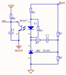
Figure 1
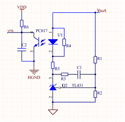
Figure 2
What kind of switching power supply loop is suitable for the two different circuits in Figure 1 and Figure 2?
Does the different positions of resistor R5 in the feedback circuit composed of TL431 and PC817 in a switching power supply have different effects on the loop?